Geometrical design rules ensure that the circuit will be manufactured correctly by checking the relative position, or syntax, of the final layout. However, there is nothing to ensure that this circuit will work. Correct functionality is left to the simulators and verifiers that manipulate circuit activity and behavior. Nevertheless, there is a middle ground between simple layout syntax and complex behavioral analysis, and it is the domain of electrical-rule checkers, or ERC.
Electrical rules are those properties of a circuit that can be determined from the geometry and connectivity without understanding the behavior. For example, the estimated power consumption of a circuit can be determined by evaluating the requirements of each device and trying to figure out how many of the devices will be active at one time. From this information, the power-carrying lines can be checked to see whether they have adequate capacity. In addition to power estimation, there are electrical rules to detect incorrect transistor ratios, short-circuits, and isolated or badly connected parts of a circuit. All these checks examine the network and look for inconsistencies. Thus, whereas design-rule checking does syntax analysis on the layout, electrical-rule checking does syntax analysis on the network.
There are several reasons to watch the power consumption of a circuit, such as limited power-carrying capacity on wires, total power limits in a single package, and cost of system manufacturing. As integrated circuits grow in size and complexity, there will be an increasing need to watch for power problems.
Metal wires that are required to carry too much power suffer metal migration, in which the atoms move within the wire, leaving a break in the conductor. In order to prevent this phenomenon, the wire must be widened to reduce its current density. Typical process rules specify the number of amps per unit width of wire. Another limit is the total amount of power, and therefore heat, that a single packaged design can dissipate before it destroys itself and its package. Standard IC packages can handle dissipations up to a few watts. However, new packaging designs employ heat fins and other cooling methods to allow greater power dissipation.
| Power estimation is dependent on the fabrication process. In nMOS, every depletion transistor that appears in a pullup configuration consumes power when pulled down to ground (see Fig. 5.11). Estimating the number of these pullups that may be pulled down allows an overall static power consumption to be derived. This estimation can use other information in the network; for example, the operation of clock signals and the interconnection of circuitry that can be determined to mutually exclude certain pulldowns. If a clock with known phases appears on the pulldown gate or on some control of that gate then it can be determined which pullups will be active in nonoverlapping times. Figure 5.12 illustrates two pullups that will not be active at the same time and can therefore be estimated to use the power of only one pullup. Figure 5.13 illustrates two coupled pullups that can also be guaranteed never to be active at the same time. When all of these heuristics have been exhausted, it must be assumed that the remaining pullups are active since their state is data-dependent. This analysis assumes static (or low-speed) power consumption. For high-speed operation, a CMOS type of analysis must also be considered. |
|
|
|
Power estimation for CMOS is different because there is usually no dissipation during stable states. Rather, CMOS circuits consume power when they switch, with the power consumption being proportional to the total load capacitance and the switching frequency. Power estimation is therefore a matter of determining the capacitance of nodes within a circuit and the rate at which the potential on these nodes changes. Power estimation for CMOS is often much more difficult than that for static nMOS.
On printed-circuit boards it is also important to determine power consumption; however, all the power-use information is described in the specification of the individual IC packages. These packages have minimum and maximum power consumption, so it is safe to sum the maximum values to determine the maximum board usage. Cooling considerations are difficult to predict. Many methods have been employed, ranging from simply allowing enough air space above the board to using freon cooling pipes running near the surface. What good is the most sophisticated electronic circuit if it burns up when plugged in?
When doing VLSI layout, it is necessary to scale transistors so that they function effectively, relative to each other. In order to achieve proper logic transition, a threshold voltage must be crossed and the speed at which this happens is determined by the relative scales or ratios of the driving components. The problem is particularly important in nMOS design, because an imbalance exists between rising and falling transition times. To ensure that such a circuit will operate correctly, an analysis of the relative transistor ratios must be done.
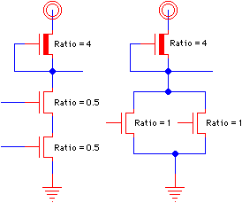
| An isolated nMOS inverter requires a pullup-to-pulldown size ratio of at least 4 : 1 which means that the length-to-width scale of the pullup must be four or more times that of the pulldown (see Fig. 5.14). When the pulldown is a series of components, the ratios of the latter are additive. When parallel transistors form a pulldown, however, each individual transistor must completely account for a proper ratio (see Fig. 5.15). This is because of the simple rule that every path from power to ground must have correct ratios of pullup and pulldown. |
|
 |
| FIGURE 5.15 Series and parallel transistor ratios. |
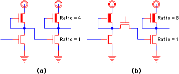
As a final rule in nMOS transistor-ratio checking, the nature of the pulldown gate must be considered. Gates that are driven directly from a pullup are considered to have a restored signal, and follow the rules for sizing in the previous paragraph. However, gates that are driven through one or more pass transistors have unrestored signals, and the ratio rule must be doubled [Mead and Conway]. Figure 5.16 illustrates this requirement, showing that the pullup on the right of Fig. 5.16(b) must change its ratio due to the nature of the pulldown gate signal. These rules are fairly straightforward to implement by traversing the circuit network and evaluating the appropriate properties. It is necessary to know the nature of all external signals to determine the restorative nature of each component. For safety, they should be assumed to be unrestored, although proper modular design dictates that all generated values should be restored.
 |
| FIGURE 5.16 Restored and unrestored transistor ratios: (a) Restored (b) Unrestored. |
| A short-circuit is a path between any two unconnected nets such as from power to ground. Detection of direct paths is simply a process of ensuring that the nets are distinct. Often this is done during node extraction, when a simple test of the net numbers will tell the truth. Also important is a check to ensure that no transistor gates power and ground signals. Although this configuration is not a static short-circuit, it does not make electrical sense and is easy to detect (see Fig. 5.17). |
|
Another static analysis is the detection of circuitry that is not properly connected. For example, when the input to a component is not connected to other parts of the circuit, it is said to be a floating input. This condition can be detected by propagating external inputs through the circuit, marking all reachable elements. When an input signal connects to the gate of a transistor, it indicates that the source and drain of the transistor are properly controlled. If other active signals appear on the source or drain end of that transistor, then the other end will be active too. By propagating the power, ground, input, and clock signals through the circuit, it is possible to check for incorrect output drive, inconsistencies of signal specifications, unconnected circuit elements, and much more. Exceptions must be allowed for artwork, which is not intended to be part of the circuit, and should not be flagged as isolated layout.
There is an unending number of specialized electrical rules. When two output signals connect such that their values combine, they are called tied outputs. This may be purposeful, but it may also be an error. Microwave circuit boards require that the wires be tapered to prevent incorrect impedance conditions. Some design environments limit the number of components that an output signal can drive (fan-out limitation) or the number of input lines that a component can accept (fan-in limitation).
All the electrical rules mentioned here can be checked at one time as the circuit network is traversed. Thus a single electrical-rule checking program is often used to check these and other circuit properties [Baker and Terman]. Such a tool can take a unified approach to checking by reducing everything to constraints on the circuit network [Karplus]. Since electrical rules tend to be specific to a particular design environment, they should be easily tailorable. The use of rule-based systems allows electrical rules to be updated easily for any given design environment and even allows the rule checker to focus its attention on the sensitive parts of a circuit [De Man et al.].
| Previous | Table of Contents | Next | Static Free Software |