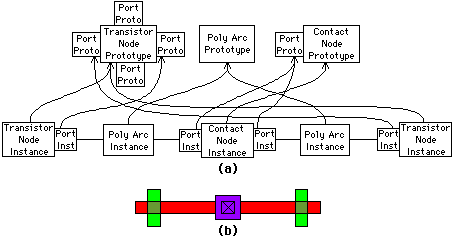
| In Electric, circuits are composed of nodes and arcs that represent components and connecting wires. For example, a transistor component connected to a contact component will be represented by two nodes and an arc (see Fig. 11.1). In addition, nodes have ports on them that are the sites of arc connections. There are two ports in this figure, one on each node at the connection site of the arc. Nodes, arcs, and ports are dynamically allocated objects in Electric, with pointers being used to link them together into networks. Each object has a basic set of attributes that hold vital information such as physical position and network neighbors. This set is extendible and can admit any attribute with any value. For example, a new attribute called "delay-time" could be created on the arc that holds a floating-point number. Also, a new attribute called "gate-contact" could be created on the transistor to hold a direct pointer to the contact node. |
|
To represent the geometry of a layout, Electric stores actual coordinates on each node and arc, expressed in half-millimicrons. Organization of this information is done with an R-tree (see Chapter 3) that locates every node and arc in a balanced geometric space [Guttman]. Thus there are two ways to access objects in the database: by topology and by geometry.
To make the representation more flexible, Electric uses the distinction between instance and prototype to aggregate common information about classes of objects. For example, the transistor node in Fig. 11.1 is a node instance object, one of which exists for every different node placed in a circuit. There is also a transistor node prototype, which exists only once to describe all its instances. Node prototypes have port prototypes on them, which are templates for possible port instances in a circuit. These port prototypes define the physical locations on the node that can be used for connection, and also the allowable arcs that may be connected. To complete the instance-prototype representation, there are arc prototypes that describe defaults for every different kind of arc. Figure 11.2 illustrates how instances and prototypes relate. Notice that port prototypes may have multiple instances on the same node (the contact node instance in this example).
 |
| FIGURE 11.2 Instance and prototype representation: (a) Representation (b) Layout. |
A technology in Electric is an object that aggregates node, port, and arc prototypes to describe a particular design environment. For example, the nMOS technology object has three arc prototypes for metal, polysilicon, and diffusion wires. It has node prototypes for enhancement and depletion transistors in addition to a series of node prototypes for interwire connections (butting, buried, and cut contacts) and intrawire connections, or pins. Instances of these prototypes can be assembled into an nMOS circuit (much like in Figs. 2.18 and 2.19). Since technologies are objects, they can also hold additional attributes. Initially, the added information includes design-rule tables and shape descriptions, but more could be handled; for example, one could add an attribute called "toxicity-level," which contains a paragraph of text describing the environmental ramifications of this semiconductor fabrication process.
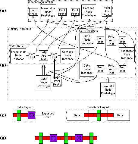
The representation of hierarchy is done through a twist of the instance-prototype scheme. Rather than have a separate class of objects to represent cells of circuitry, the node-instance object can point to either primitive or complex prototypes. Whereas primitive node prototypes are defined in the environments as described, complex node prototypes are actually cells that contains other node, arc, and port instances (see Fig. 11.3). Port prototypes on complex node prototypes (that is, ports on cells) are actually references to ports on nodes inside of the cell (see the heavy line in the figure). This notion of "exporting" ports combines with the complex node-prototype scheme to provide a uniform representation of components in a hierarchical circuit. Although the prototype objects vary slightly in their information content, the node- and port-instance objects are the same regardless of whether they describe primitive or complex prototypes.
Electric also extends the concept of a cell so that there can be different views (schematics, layout, VHDL, etc.) and multiple versions of each view. A particular view and version of a cell is called a facet, and thus creates a view hierarchy for each cell. This idea is similar to the Oct/VEM work [Harrison, Moore, Spickelmier and Newton]
 |
| FIGURE 11.3 Hierarchical representation: (a) Primitive prototypes in a technology (b) Complex node prototypes, or cells (c) Cell layouts (d) Exploded layout. |
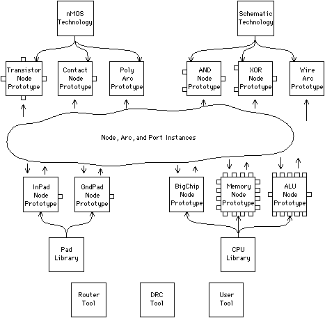
Everything in Electric is an object with extendible attribute-value pairs. This section has already mentioned node, arc, and port instances; node, arc, and port prototypes; and technologies. There are also library objects that aggregate complex node prototypes, and tool objects that operate on the circuitry (see Fig. 11.4). Tool objects contain many attributes that are actually code routines for performing the essential synthesis and analysis functions.
 |
| FIGURE 11.4 All objects of the Electric database. |
As an example of how attribute flexibility works, the operation of a typical functional simulator will be described. Functional simulators can either simulate the contents of a cell or use a behavioral description, which more efficiently describes the contents. All primitive node prototypes start with such a behavioral description so that the simulator will not attempt to examine their contents. Whenever a cell is to be behaviorally described, the designer enters that information in the same place on the complex node prototype. The simulator merely checks for the existence of the behavior attribute on the prototype when deciding how to handle a node. Thus, the Electric representation is powerful enough to contain any piece of information and flexible enough to organize that information sensibly.
| Previous | Table of Contents | Next | Static Free Software |