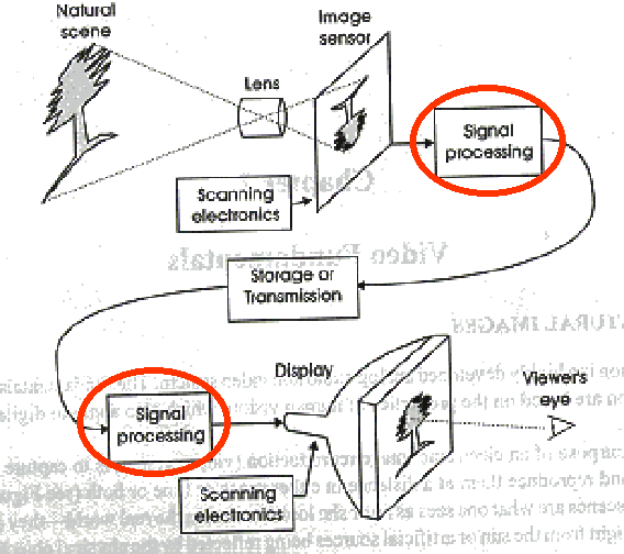
The first question we would like to answer is: what do we mean nowadays for video processing? In the past, more or less till the end of the 80’s there where two distinct worlds: an analog TV world and a digital computer world. All TV processing from the camera to the receiver was based on analog processing, analog modulation and analog recording. With the progress of digital technology, a part of the analog processing could be implemented by digital circuits with consistent advantages in terms of reproducibility of the circuits leading to cost and stability advantages, and noise sensitivity leading to quality advantages. At the end of the 80’s completely new video processing possibilities became feasible by digital circuits. Today, image compression and decompression is the dominant digital video processing in term of importance and complexity of the all TV chain.

Figure 1. Schematic representation of a TV chain.
In the near future digital processing will be used to pass from standard resolution TV to HDTV for which compression and decompression is a must, considering the bandwidth that it would require for transmission. Other applications will be found at the level of the camera to increase the image quality by increasing the number of bit from 8 to 10 or 12 for each pixel, or by using appropriate processing aiming at compensating the sensors limitations (image enhancement by non-linear filtering and processing) . Digital processing will also enter into the studio for digital recording, editing and 50/60 Hz standard conversions. Today the high communications bandwidth required by uncompressed digital video necessary for editing and recording operations, between the studio devices limits the use of full digital video and digital video processing at studio level.
Video Compression
Why video compression has become the dominant video processing application of TV? An analog TV channel only needs a 5 MHz analog channel for the transmission, conversely in case of digital video with: 8 bit A/D, 720 pixels for 576 lines (54 MHz sampling rate) we need a transmission channel with a capacity of 168.8 Mbit/s!!! In case of digital HDTV the capacity for: 10 bit A/D, 1920 pixels 1152 lines raise up to1.1 Gbit/s!!! No affordable applications, in terms of cost, are thus possible without video compression.
These reasons have raised also the need of worldwide standards for video compression so as to achieve interoperability and compatibility among devices and operators. H.261 is the names given to the first digital video compression standard specifically designed for videoconference applications, MPEG-1 is the name for the one designed for CD storage (up to 1.5 Mbit/s) applications, MPEG-2 for digital TV and HDTV respectively from 4 up to 9 Mb/s for TV, or up to 20 Mb/s for HDTV; H.263 for videoconferencing at very low bit rates (16 - 128 kb/s). All these standards can be better considered as a family of standards sharing quite similar processing algorithms and features.
All of them are based on the same basic philosophy:
MPEG-2 Video Compression
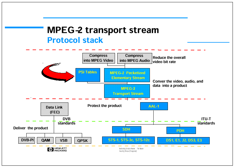
MPEG-2 is a complete standard that specifies all stages from video acquisition up to the interface with the communication protocols. Figure 2 reports a schematic diagram of how MPEG-2 provides after compression a transport layer. Audio and video compressed bit-streams are multiplexed and put in packets in a suitable transport format. This part of the processing cannot be classified as video processing, and is not considered here in details.
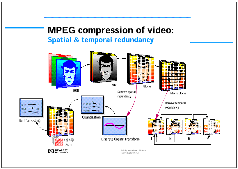
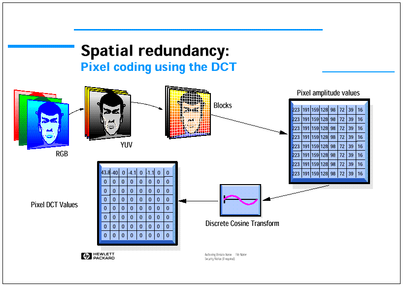
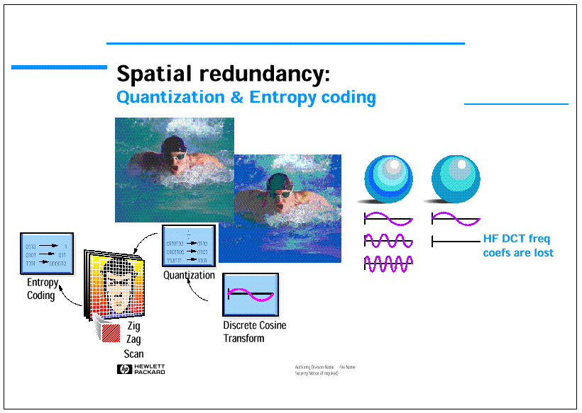
In more details (see Figures 4 and 5) spatial redundancy is reduced applying 8 times horizontally and 8 times vertically a 8x1 DCT transform. Then transform coefficients are quantized, thus reducing to zero small high frequency coefficients, scanned in zig-zag order starting from the DC coefficient at the upper left corner of the block and coded using Huffman tables referred also as Variable Length Coding (VLC).
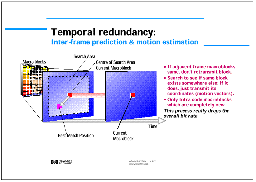
The reduction of temporal redundancy is the process that drastically reduces the bit rate and enables to achieve high compression rates. It is based on the principle of finding the current macro-block in already transmitted pictures at the same position in the image or displaced by a so-called "motion vector" (see figure 6). Since an exact copy of the macro-block is not guaranteed to be found, the macro-block that has the lowest average error is chosen as reference macro-block. The "error macro-block" is then processed so as to reduce the spatial redundancy, if any, by means of the above mentioned procedure and transmitted so as to be able to reconstruct the desired macro-block disposing of the "motion vector" indicating the reference and the relative error.
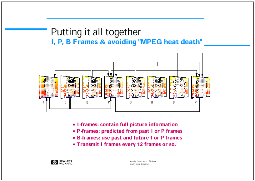
Figure 7 reports the so-called MPEG-2 Group of Picture Structure that shows that images are classified as I (Intra), P (Predicted) and B (Bi-directionally interpolated). The standard specifies that Intra image macro-block can only be processed to reduce spatial redundancy, P image macro-block can also be processed to reduce the temporal redundancy referring only to past I or P frames, B image macro-block can also be processed using an interpolation of past and future reference macro-block. Obviously B macro-block can also be coded as Intra or Predicted if it is found to convenient for the compression. Note that since B picture can use as reference both past and future I or P frames, the MPEG-2 image transmission order is different from the display order, B picture are transmitted in the compressed bit-stream after the relative I and P pictures.
Complexity of MPEG Video Processing
At the end of the 80’s there have been a lot of discussions about the complexity of implementing DCT transforms in real-time at video rate. Blocks of 8x8 have been chosen instead of 16x16 in order to reduce the complexity of the transform. The main objective was to avoid complex processing at the decoder side. With this goal many DCT optimized implementations have appeared in both form of dedicated chips and software using reduced number of multiplication and additions.
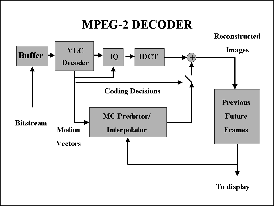
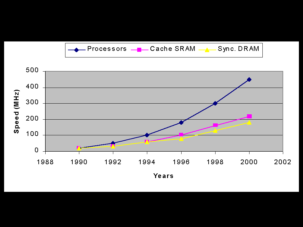
Nowadays, digital technology has made many progresses in terms of speed increase and processing performance for which the DCT coding or decoding is not anymore a critical issue. If we look to Figure 8 we can find a schematic block diagram of an MPEG-2 decoder that is very similar to the ones of the other compression standards. A buffer is needed to receive at a constant bit-rate the compressed bits that during decoding are not "consumed" at a constant rate. VLD is a relatively simple processing that can be implemented by means of look-up tables or memories. Being a bit-wise processing, it cannot be parallelized and results quite inefficient to be implemented in general purpose processors. This is the reason for which new multimedia processors such as Philips "Trimedia" use specific VLC/VLD units for entropy coding. The more costly elements of the MPEG-2 decoder are the memories for the storage of past and future reference frames and the handling of the data flow between the Motion Compensated Interpolator unit and the Reference video memories.
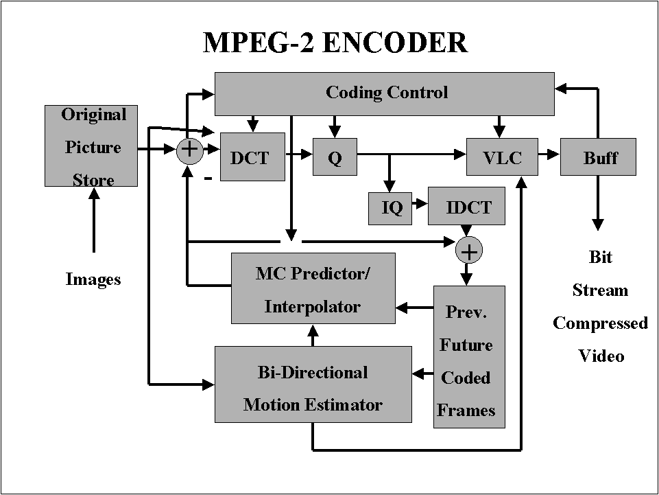
For an MPEG-2 encoder, see Figure 9, the situation is very different. First of all we can recognize a path that implements a complete MPEG-2 decoder, necessary to reconstruct reference images as they are found at the decoder size. Then we have a motion estimation block (Bi-directional motion estimator) that has the goal of finding the motion vector, and a block that selects and controls the macro-block encoding modes. As discussed in the previous paragraphs, the way to find the best motion vectors as well as the way to chose the right coding for each macro-block is not specified by the standard. Therefore, very simple (with limited quality performance), or extremely complex algorithms (with high quality performance) can be implemented for these functions. Moreover, MPEG-2 allows the dynamic definition of the GOP structure making possible many possibilities of coding modes. In general two are the critical issues of an MPEG-2 encoder: the motion estimation processor and the handling of the complex data flow with relative bandwidth problems between original and coded frame memories, motion estimation processor and the coding control unit.
We have also to mention that the coding modes of MPEG-2 are much more complex of what could seem from this brief description. In fact, existing TV is based on interlaced images and the processing all coding modes can be applied in distinct ways to "frame" blocks and macro-blocks or on "field" blocks and macro-blocks. The same applies for motion estimation for which we can use both field-based or frame-based vectors. Moreover all references for predictions can be made on true image pixels or on "virtual" image pixels obtained by bi-linear interpolations as shown in Figure 10.
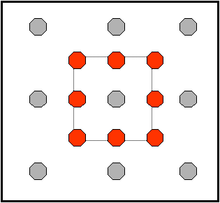
In this case also, motion vectors with half pixel precision need to be estimated. The possibility of using all these possible encoding modes largely increases the quality of the compressed video, but it might become extremely demanding in terms of processing complexity.
The challenge of MPEG-2 encoder designer is to find the best trade-off between the complexity of the implemented algorithms and the quality of the compressed video. Architectural and algorithmic issues are very strictly related in MPEG-2 encoder architectures.
Digital Video and Computer Graphics
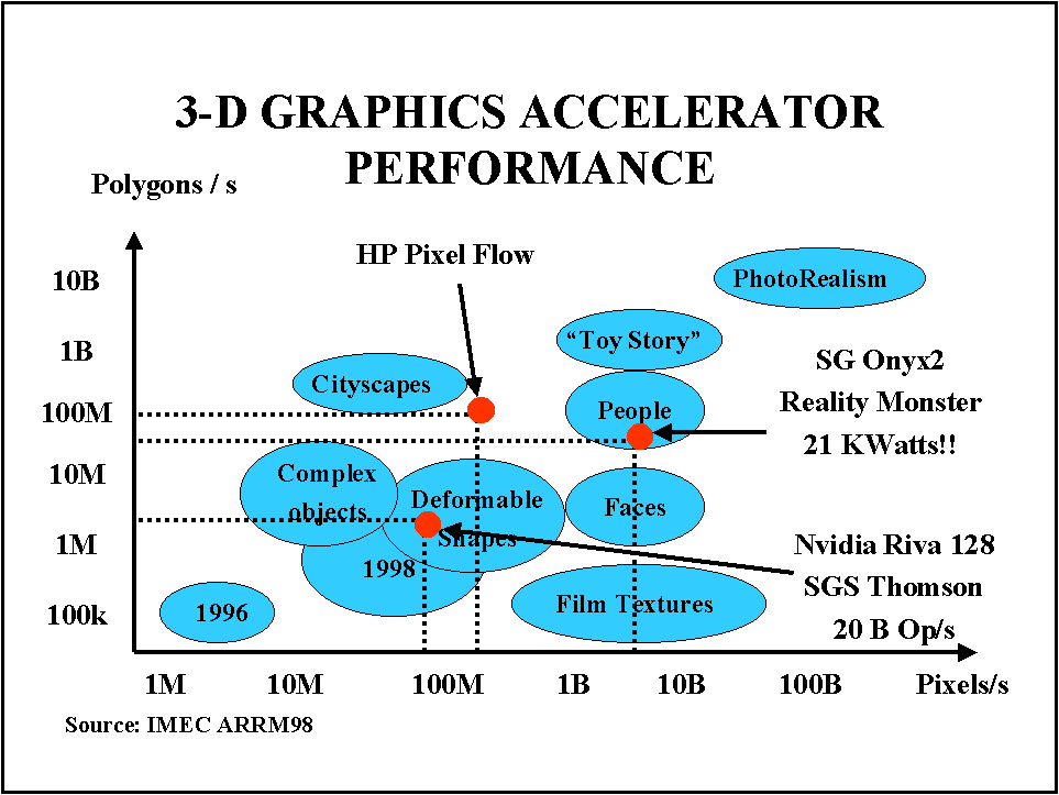
In the past digital video on computers was equivalent to computer graphics. Differently from the TV world all processing was obviously digital mainly treating synthetic images from 2-D or 3-D models. The concept of real-time computer graphic application was very approximate since usually the application was intended to run as fast as possible on the available processors using in parallel graphic accelerators for the arithmetic operations on pixels.
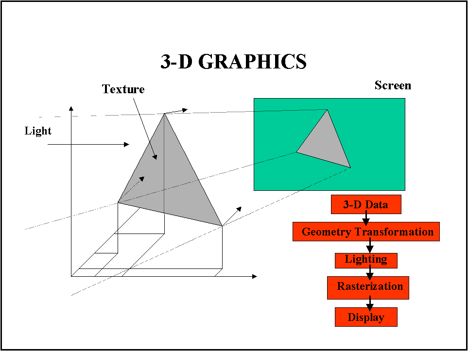
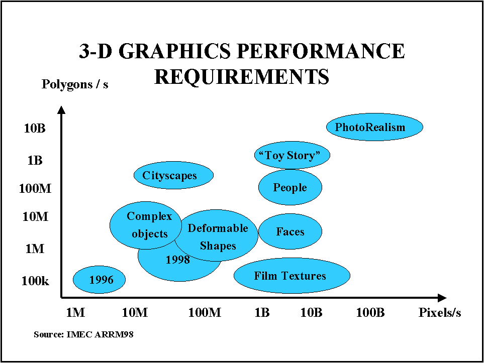
TV, Computer Graphics and Multimedia: MPEG-4?
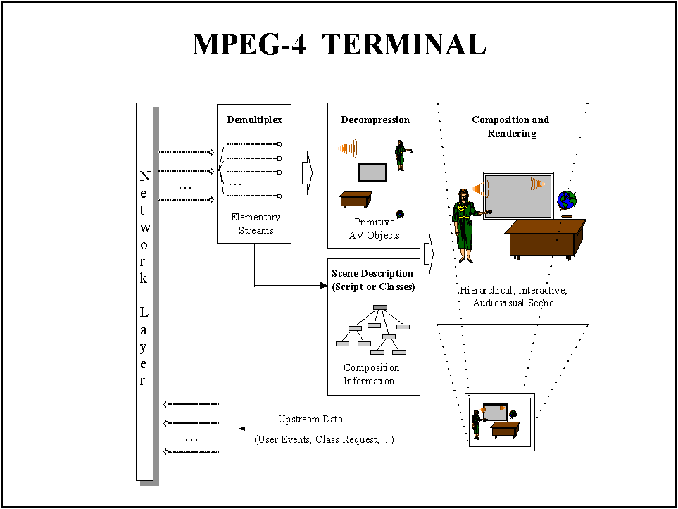
The new MPEG-4 multimedia standard, which was defined as draft ISO international standard in October 98, is trying the ambitious challenge of putting together the world of natural video and TV with the world of computer and computer graphics.
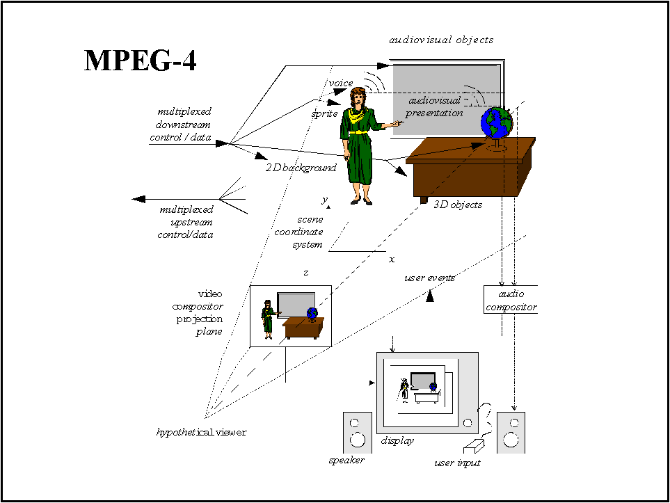
In MPEG-4 we can find in fact both natural compressed video and 2-D and 3-D models. The standard is based on the concept of elementary streams that represents and carry the information of a single "object" that can be of any type "natural" or "synthetic", audio or video.
Figure 13, reports an example of what can be the content of a MPEG-4 scene. Natural and 2-D and 3-D synthetic audio-visual objects are received and composed in a scene as seen by an hypothetical viewer.
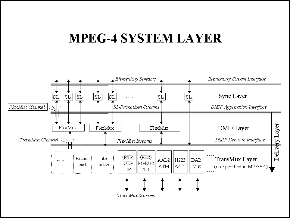
The processing related to MPEG-4 Systems layer cannot considered as video processing and is very similar to the packet processing typical to network communication.
An MPEG-4 terminal can be schematized as shown in Figure 15. The communication network provides the stream that is demultiplexed into a set of "elementary streams". Each "elementary stream" is decoded into audio/video objects. Using the scene description transmitted with the elementary streams all object are "composed" in the video memory all together according to the size, view angle and position in the space and then "rendered" on the display, which can be interactive and originating a upstream data due to the user interaction and sent back to the MPEG-4 encoder.
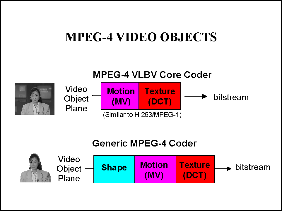
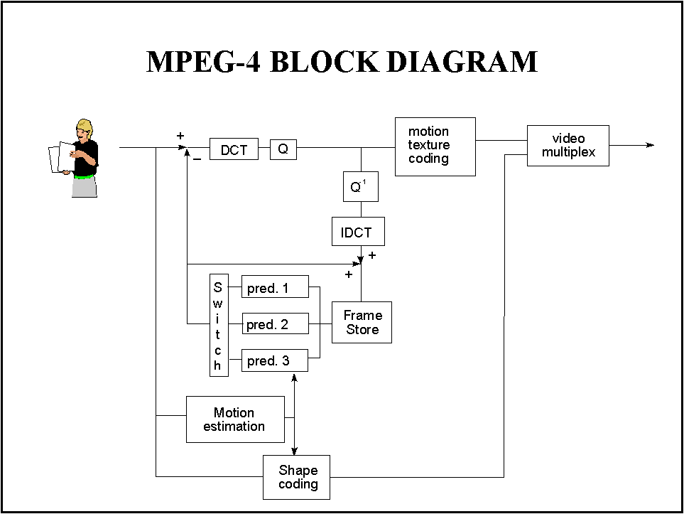
MPEG-4 systems, therefore implement not only the classical MPEG-2-like compression/decompression processing and functionality but also computer graphics processing such as "composition" and "rendering". The main difference comparing to natural video of MPEG-1, MPEG-2, H.263, is the introduction of "shape coding" enabling the use of arbitrarily shaped video objects as illustrated in Figure 16. Shape coding information is based on macro-block data structures and arithmetic coding for the contour information associated at each boundary block.
Video Processing Architectures: Generalities
In general, we can classify the circuits implementing video processing in four families:
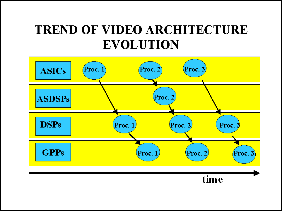
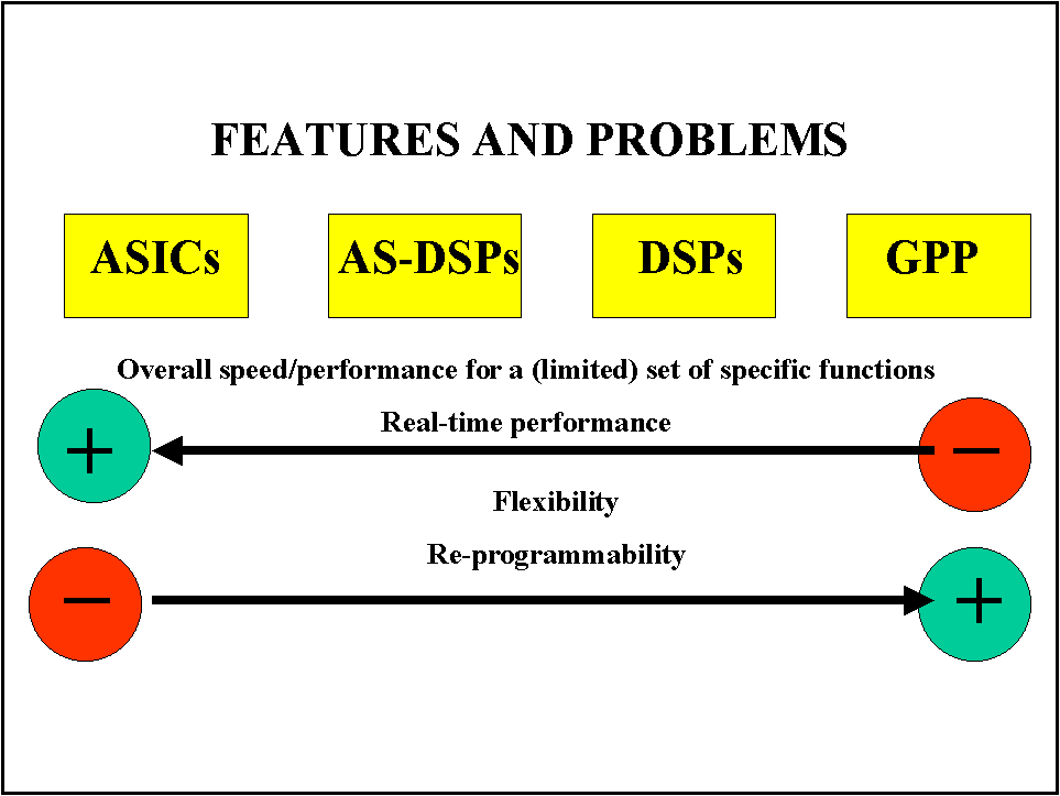
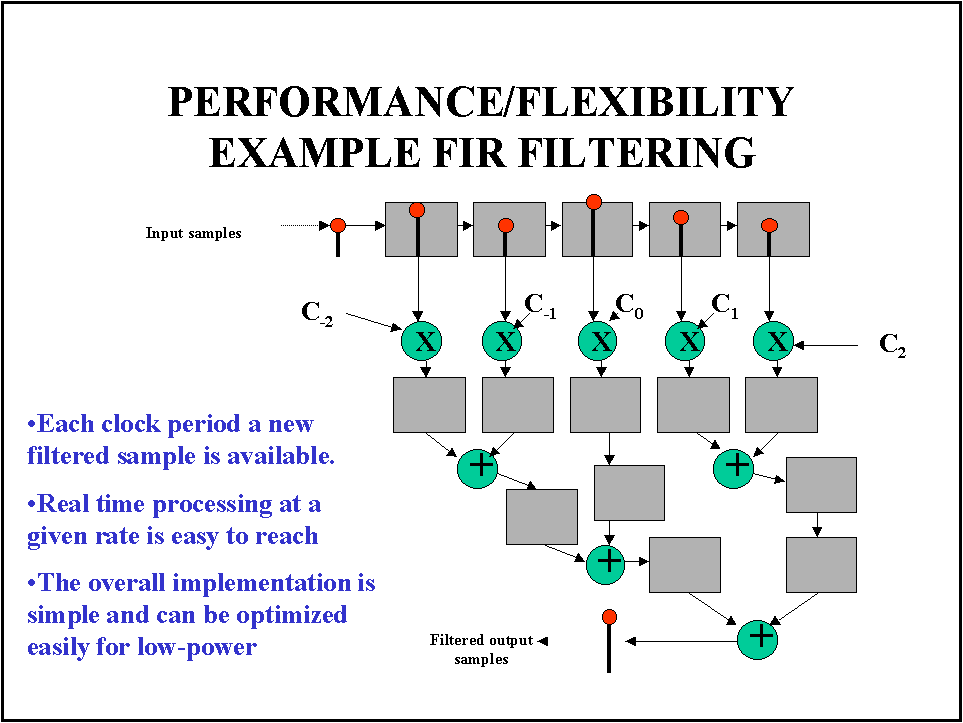
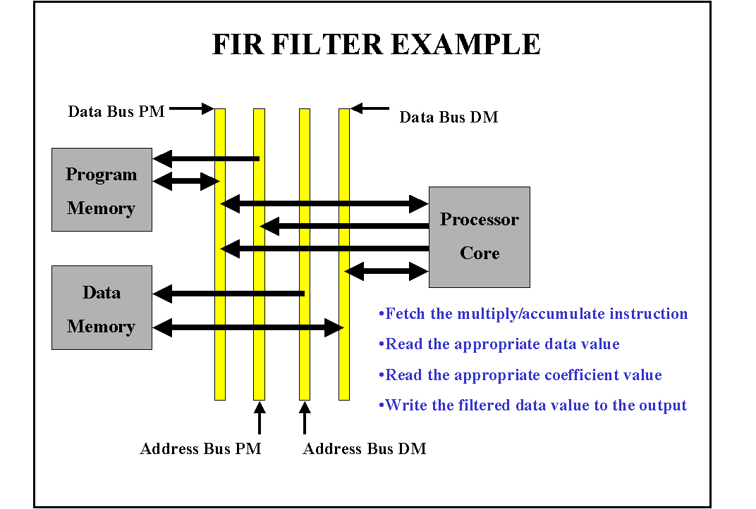
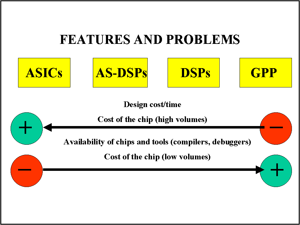
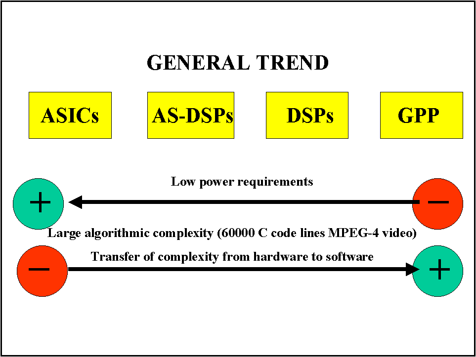
These considerations lead to clear advantages in terms of cost for ASICs when high volumes are required (see Figure 23). Simpler circuits that require smaller silicon surface areas are the right solution for set-top boxes and application for high volumes (MPEG-2 decoders for digital TV broadcasting for instance). In these cases the high development costs and the lack of debugging and software tools for the simulation and design do not constitute a serious drawback. Modifications of the algorithms and the introduction of new versions are not possible, but are not required by this kind of applications. Conversely, for low volume applications, the use of programmable solutions immediately available on the market, well supported by compilers, debuggers and simulation tools that can effectively speed up the development time and cost, might be the right solution. The much higher cost of the programmable processor, in some cases become acceptable for relatively low volume of devices.
Another conflicting trend between hardwired and programmable solutions can be found by the need of designing low-power solutions required by the increasing importance of portable device applications and necessary to reduce the increasing power dissipated by high performance processors (see Figure 24). This trend conflicts with the need of transferring the increasing complexity of processing algorithms from the architecture to the software which is much easier and faster to be modified corrected and debugged. The optimization of memory size and accesses, clock frequency, and other architectural features that yield low-power consumption are only possible on ASICs architectures.
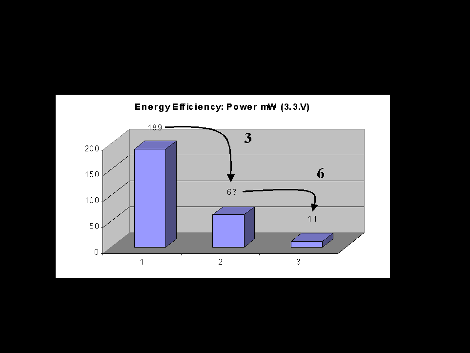
What is the range of power consumption reduction that can be reached passing from a GPP to an ASIC? It is difficult to answer to this question with a single figure, it depend by architecture to architecture, processing by processing. For instance Figure 24 reports the power dissipation of a 2-D convolution with 3x3 filter kernel on a 256x256 image on three different architectures. The result is that a ARM RISC implementation, beside being slower that the other alternatives and so providing a under-estimated result, is about 3 times more demanding than a FPGA implementation and 18 times more than an ASIC based one. The example of the IMAGE motion estimation chip that is reported at the end of this document shows that much higher reduction factors (even more than two orders of magnitude) can be reached by low-power optimized ASIC architectures for specific processing tasks when compared to GPPs providing the same performance.
Motion Estimation Case Study
Block motion estimation for high quality video compression applications (i.e. digital TV broadcasting, multimedia content production…..) is a typical example for which GPP architectures are not a good choice for the implementation.
Motion estimation is indeed the most computational demanding stage of video compression at the encoder side. For normal resolution TV we have to encode 1620 macro-block per frame, with 25 frame per second. Roughly, to search a motion vector error we need to perform about 510 arithmetic operations on data from 8 to 16 bits. The number of vector displacements depends on the search window size that should be large for guaranteeing high quality coding. For instance for sport sequences a size of about 100x100 is required. This leads to about 206 x 109 arithmetic operations per second on 8 to 16 data. Even if we are able to select an "intelligent" search algorithm that reduces from one up to two orders of magnitude the number of search points the number of operations remain extremely high and not feasible by for state of the art GPPs. Moreover, 32 or 64 bit processing arithmetic cores are wasted when operations only on 8 to 16 bits are necessary. Completely different architectures that implement a high level of parallelism at bit level are necessary.
If we want to be more accurate, we can notice that B pictures require both forward and backward motion estimation, and for instance for TV applications each macro-block can use the best between frame-based or field-based motion vectors at full or half pixel resolution level. Therefore, we realize that the real processing needs can increase of more than a factor 10, if all possible motion vectors are estimated.
Another reason for which ASICS or AP-DSPs are an interesting and actual choice for motion estimation is the still unsolved need of motion estimation for TV displays. Large TV displays require to double the refresh rate to avoid the annoying flickering phenomenon appearing on the side portions of large screens. A conversion of interlaced content from 50 to 100 Hz by the simple doubling of each field provides satisfactory results in there is no motion. In case of moving objects the image quality provided by field doubling is low and motion compensated interpolation is necessary to reconstruct the movement phase of the interpolated images. An efficient and low-cost motion estimation stage is necessary for high quality up-conversion on TV displays.
IMAGE a Motion Estimation Chip for MPEG-2 applications.
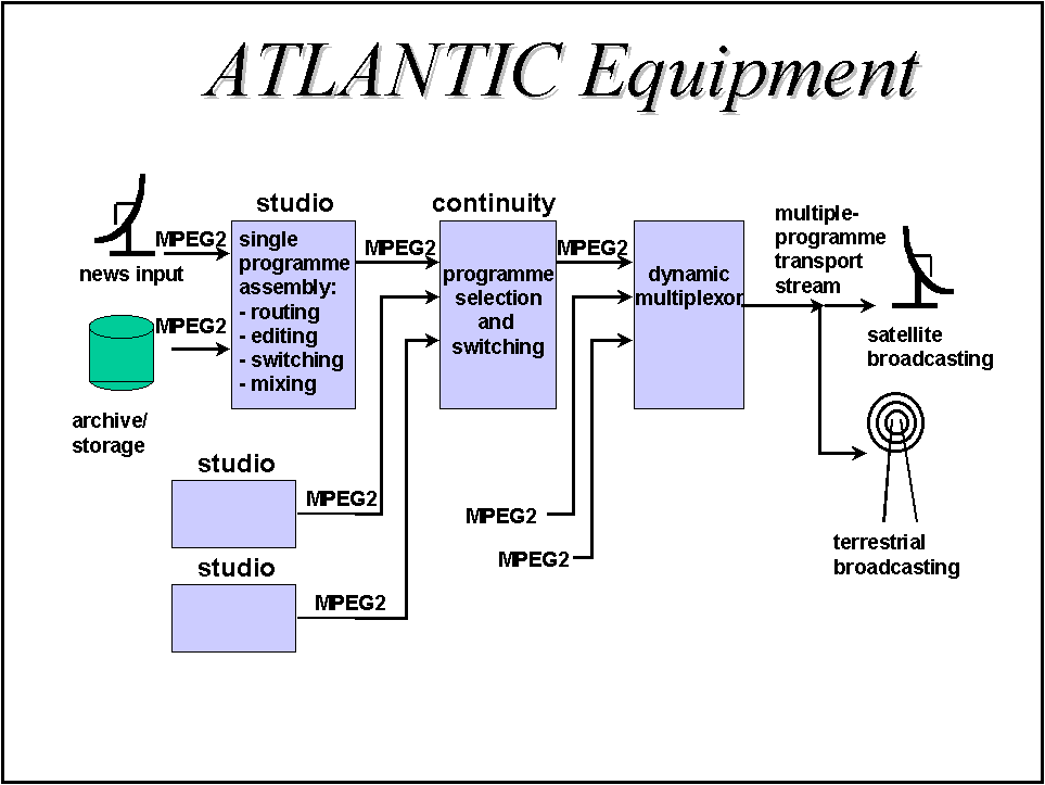
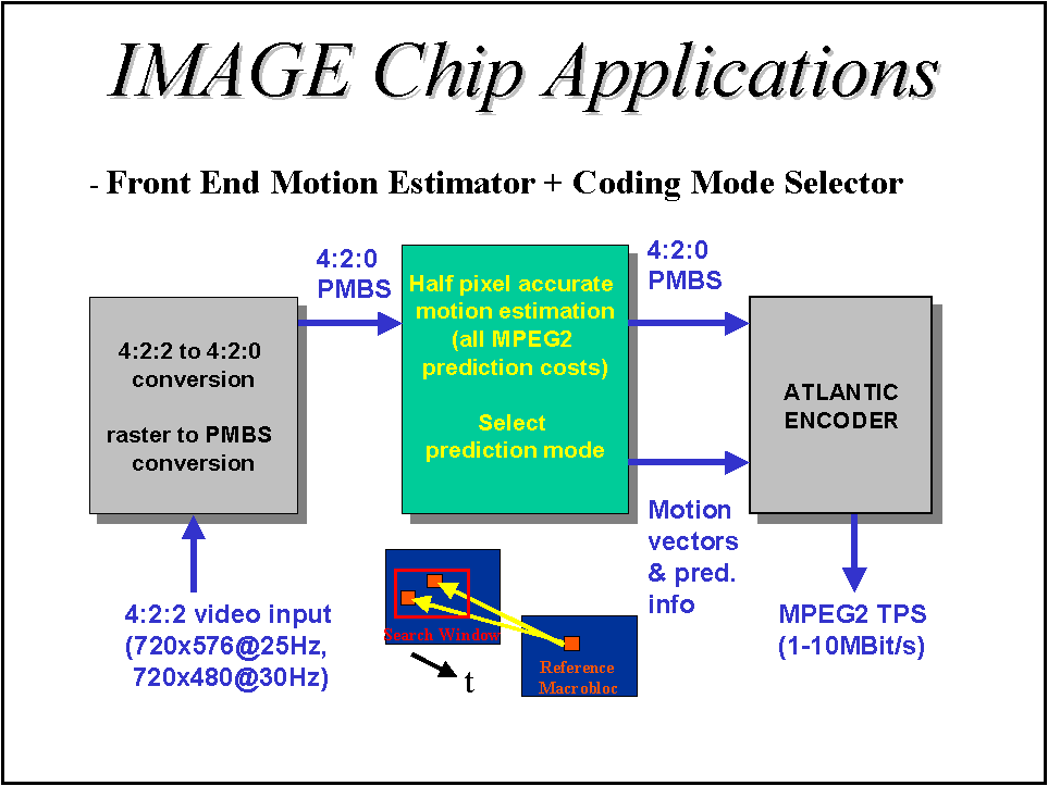
We briefly describe the characteristics of a motion estimation chip designed in the C3I laboratory of the EPFL in the framework of the ATLANTIC european project in collaboration with the BBC, CSELT, Snell&Wilcox and Fraunhofer Institute. IMAGE is an acronim for Integrated MIMD Architecture for Genetic motion Estimation. The requirements for the chip was to provide estimations for MPEG-2 encoders in very large search windows for forward, backward, field-based, frame-based, full-pel, half-pel precision motion vectors. Figure 27 and 28 report the MPEG-2 broadcasting chain and the main input-output specification of the chip. The same chip is also required to provide the result of the candidate motion compensation mode (forward, backward, filed, frame, intra), and the selection of the corresponding best coding decision. Since all these operation are macro-block based, they share the same level of parallelism of motion estimation algorithms.
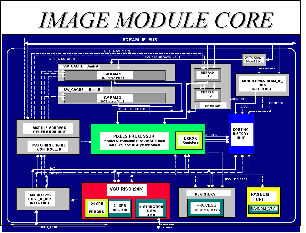
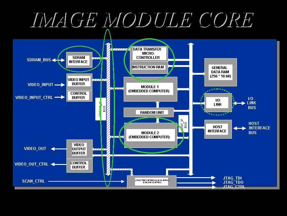
The basic architectural idea has been to design a processing engine extremely efficient in getting the mean absolute difference between macro-blocks (matching error) with fast access to a large image section (search window size). By extremely efficient it is meant exploiting as much as possible the parallelism intrinsic to pixel operations on 16x16 block of pixels and able to access randomly any position in the search window without useless waiting times (i.e. providing the engine with the sufficient memory bandwidth to fully exploit its processing power). Figure 29 reports the block diagram of the "block-matching" engine. We can notice in the center the "pixel processor" for the parallel execution of the macro-block difference, two cache memory banks for the storage of the current macro-block and for the search window reference, a RISC processor for the handling of the genetic motion estimation algorithm and for the communications between processing units. The basic processing unit of Figure 29 is then reported in the general architecture of the chip reported in Figure 30. We can notice two macro-block processing units in parallel, the various I/O modules for the communication with the external frame memory and the communication interfaces for cascading the chip for forward and backward motion estimation and for larger search window sizes. As mentioned discussion data intensive applications one of the main difficulty of the chip design is the correct balancing of the processing time of the various units and the optimization of the various communications between modules. It is fundamental that all module processing are scheduled so as to avoid wait times and the communication busses have the necessary bandwidth.
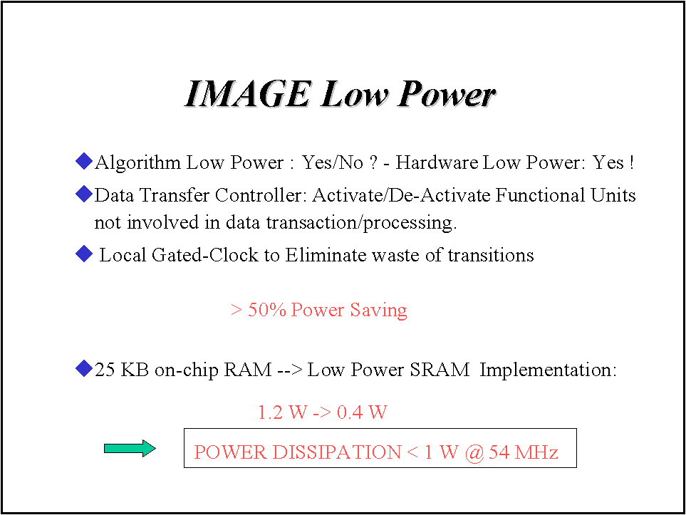
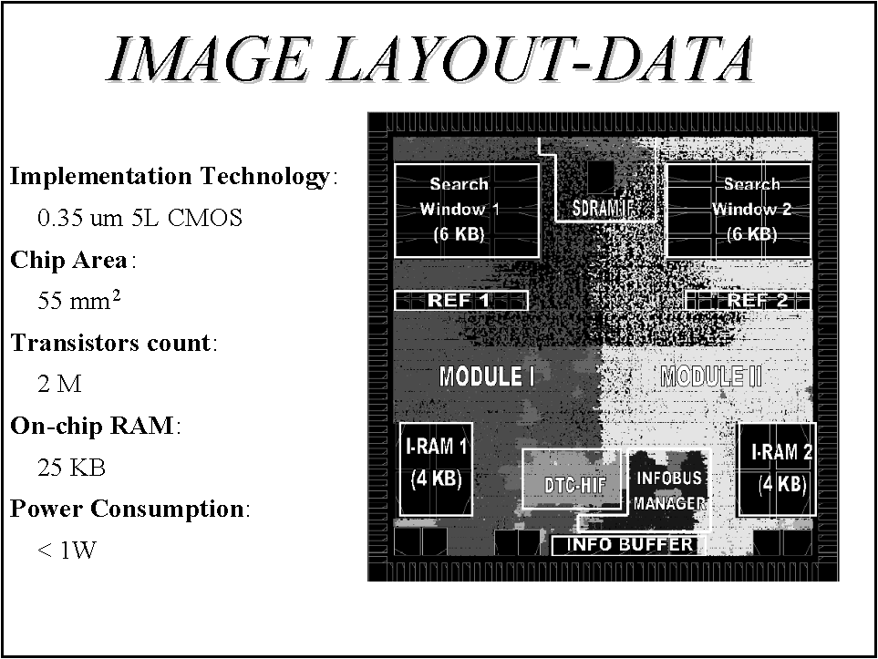
Low power optimizations are summarized in figure 31. Deactivation of processing units, local gated clocks and implementation of a low-power internal SRAM as cache memory enabled to keep power dissipation below 1W. Figure 32 reports the final layout of the chip with the main design parameters.
In conclusion, the chip IMAGE can be classified as an AS-DSP for its high programmability where the application specific for which a special hardware is used is the calculation of macro-block differences. Its performance for motion estimation are much higher than any state of the art GPPs and obtained with a relatively small chip dissipating less than 1W when providing real-time motion estimation for MPEG-2 video compression. More details about the IMAGE chip can be found in: F. Mombers, M. Gumm and Al. "IMAGE: a low-cost low-power video processor for high quality motion estimation in MPEG-2 encoding", IEEE Trans. on Consumer Electronics, Vol 44, No. 3 August 1998, pp. 774-783.
