Low and High Shelving Filters Next  |  Prev  |  Up  |  Top  |  Index  |  JOS Index  |  JOS Pubs  |  JOS Home  |  Search


Low and High Shelving Filters

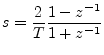
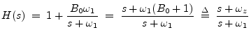
The analog transfer function for a low shelf is given by [102,6]

$\displaystyle H(s)
\;=\; 1 + \frac{B_0\omega_1}{s+\omega_1}
\;=\; \frac{s+\omega_1(B_0+1)}{s+\omega_1}
\;\isdef \; \frac{s+\omega_z}{s+\omega_1}
$

where $ B_0$ is the dc boost amount (at $ s=0$), and the high-frequency gain ($ s=\infty$) is constrained to be $ 1$. The transition frequency dividing low and high frequency regions is $ \omega_1$. See Appendix C for a development of $ s$-plane analysis of analog (continuous-time) filters.

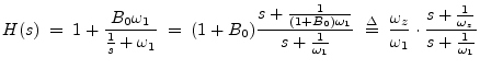
A high shelf is obtained from a low shelf by the conformal mapping $ s \leftarrow 1/s$, which interchanges high and low frequencies, i.e.,

$\displaystyle H(s) \;=\; 1 + \frac{B_0\omega_1}{\frac{1}{s}+\omega_1}
\;=\; (1...
...{\omega_z}{\omega_1} \cdot \frac{s + \frac{1}{\omega_z}}{s+\frac{1}{\omega_1}}
$

In this case, the dc gain is 1 and the high-frequency gain approaches $ 1+B_0 = \omega_z/\omega_1$.

To convert these analog-filter transfer functions to digital form, we apply the bilinear transform:

$\displaystyle s = \frac{2}{T}\frac{1-z^{-1}}{1+z^{-1}}
$

where $ T$ denotes the sampling interval in seconds.


Subsections
Next  |  Prev  |  Up  |  Top  |  Index  |  JOS Index  |  JOS Pubs  |  JOS Home  |  Search

[How to cite this work] [Order a printed hardcopy]

``Introduction to Digital Filters with Audio Applications'', by Julius O. Smith III, (August 2006 Edition).
Copyright © 2007-02-02 by Julius O. Smith III
Center for Computer Research in Music and Acoustics (CCRMA),   Stanford University
CCRMA  [Automatic-links disclaimer]