Applying Layout
This chapter was written with the participation of Peter Uhnák ([email protected]).
A layout is the visualization representation along a two-dimensional plan of elements, typically edges and nodes. A layout makes a visualization not only aesthetic but also comprehensible. Roassal offers numerous different layouts and supports the composition of layouts.
Consider the following example (Figure 0.1):
	view := RTView new.
	es := (RTEllipse new size: 12; color: Color blue)
		elementsOn: (1 to: 30).
	view addAll: es.

	RTEdgeBuilder new
		view: view;
		elements: es;
		connectFrom: [ :value | value // 2 ].

	es do: [ :each | each translateTo: (250 atRandom) @ (250 atRandom) ].
	view
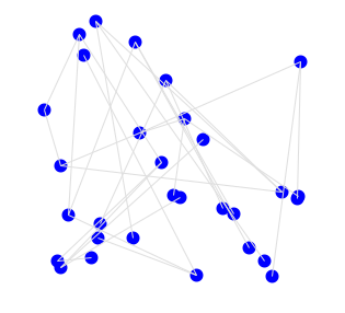
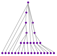
The script builds some elements and edges that link these elements. Each element is translated to a random location. Applying the RTTreeLayout layout highlights the structure from the connection between the elements (Figure 0.2):
	view := RTView new.
	es := (RTEllipse new size: 12; color: Color blue)
		elementsOn: (1 to: 30).
	view addAll: es.

	RTEdgeBuilder new
		view: view;
		elements: es;
		connectFrom: [ :value | value // 2 ].

	es do: [ :each | each translateTo: (250 atRandom) @ (250 atRandom) ].
	RTTreeLayout on: es.
	view
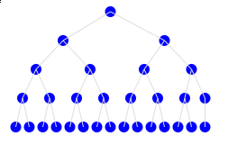
The layout reveals that the elements form a binary tree and one can distinguish what the top root node is and what the leaves are.
Roassal offers over 30 different layouts, each useful in its own rights.
1. Element-based Layouts
Element-based layouts are a particular set of layouts in Roassal which do not consider edges to determine element locations. Instead of using edges, an element-based layout uses element size, shape or position within a group. Edges are not forbidden: they are simply not used by the layout.
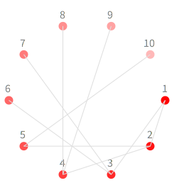
1.1. Circle Layouts
Circle layouts arrange elements along a geometrical circle. The order of the elements, as with all circle-based layouts, is the same as the collection on which the layout operates.
	v := RTView new.

	es := (RTEllipse new size: 12) elementsOn: (1 to: 10).
	v addAll: es.
	es @ RTLabeled.

	RTMetricNormalizer new
		elements: es;
		normalizeColor: #yourself using: (Array with: Color red with: Color lightRed).

	RTEdgeBuilder new
		view: v;
		elements: es;
		connectFrom: [ :value | value // 2 ].

	RTCircleLayout new on: es.
	v
A circular layout may be parametrized along several properties:
	RTCircleLayout new
		initialIncrementalAngle: 30 degreesToRadians;
		initialAngle: 15 degreesToRadians;
		initialRadius: 200;
		on: es.
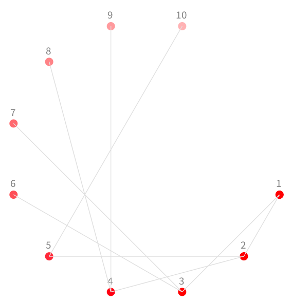
Without any option, the circle layout distributes all the elements evenly along a circle (2pi/elements size). Additionally radius can be either set absolutely via initialRadius:, or as a scalable factor scaleBy: - then the radius will be elements size * scaleFactor.
It is important to note that RTCircleLayout does not take into consideration the size of the elements; this is enough when the elements are uniform, however if their sizes vary, different layouts may be considered.
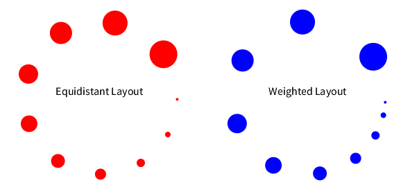
Variants of the default circle layout, named equidistant and weighted layouts, are also available:
-
RTEquidistantCircleLayoutmakes sure that there is the same distance between each element. -
RTWeightedCircleLayouton the other hand adds spacing based on the size of the elements. Thus there will be less space between smaller elements, and more space between large ones.
So now if we apply layout on non-uniform elements we get:
	v := RTView new.
	elements := (RTEllipse new color: Color red; size: [:vv | vv * 4 ])
		elementsOn: (1 to: 10).
	v addAll: elements.
	RTEquidistantCircleLayout on: elements.
	elements translateBy: -150 @ 0.
	v add: ((RTLabel new elementOn: 'Equidistant Layout') translateTo: -40 @ 100).

	es := (RTEllipse new color: Color blue; size: [:vv | vv * 4 ])
		elementsOn: (1 to: 10).
	v addAll: es.
	RTWeightedCircleLayout on: es.
	es translateBy: 150 @ 0.
	v add: ((RTLabel new elementOn: 'Weighted Layout') translateTo: 260 @ 100).
	v
1.2. Flow Layouts
A flow layout arranges elements in a 'flowing' manner. While we could consider circle layouts to be also a flow in a clockwise direction, layouts presented here provide flow by lines and columns.
1.2.1. Flow and Grid Layouts
The flow layout arranges elements in lines, each line flowing from left to right; Horizontal flow on the other hand is in columns, flowing from top to bottom.
	v := RTView new.

	shape := RTCompositeShape new.
	shape add: RTLabel new.
	shape add: (RTBox new
		color: Color transparent; borderColor: Color black).
	es := RTGroup
		with: (shape elementOn: RTFlowLayout)
		with: (shape elementOn: RTHorizontalFlowLayout)
		with: (shape elementOn: RTGridLayout)
		with: (shape elementOn: RTCellLayout).
	v addAll: es.

	RTNest new
		for: es
		inShape: #second
		add: [ :group :layout |
			group addAll: ((RTBox new size: [:m | m * 10])
				elementsOn: (1 to: 6)).
			layout new on: group.
		].

	RTCellLayout new gapSize: 10; on: es.

	(v elements allButFirst: 4) @ (RTLabeled new
		color: Color black; center).
	v
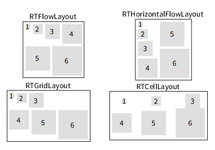
Flow layouts vertically line up elements according to their size. The layout may be configured with a maximum total width (maxWidth:). For Grid and Cell layout this limit is instead number of items in the line (lineItemsCount:).
By default a flow layout try to fill a roughly rectangular area, while a grid layout approximate the golden ratio.
1.2.2. Alignment
Cells in Flow layouts can be aligned:
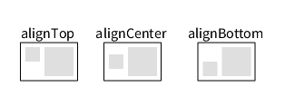
To align RTHorizontalFlowLayout use alignTop for left, and alignBottom for right alignment.
1.2.3. Line Layouts
Two line layouts are offered: RTVerticalLineLayout and RTHorizontalLineLayout to layout, vertically and horizontally, respectively (Figure 1.6).
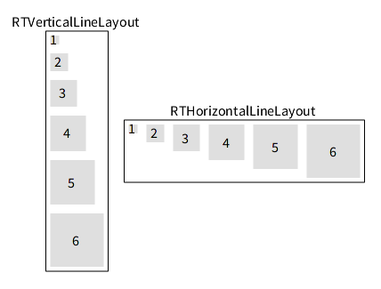
RTVerticalLineLayout and RTHorizontalLineLayout
Here is an example of the horizontal line layout:
	v := RTView new.
	es := (RTBox new size: #yourself) elementsOn: (10 to: 40 by: 5).
	v addAll: es.
	RTHorizontalLineLayout on: es.
	v
Replacing RTHorizontalLineLayout by RTVerticalLineLayout triggers the vertical line layout instead.
2. Edge-driven layouts
Edge-driven layouts determine the location of an element based on the edges linking these elements.
2.1. Tree Layout
The beginning of this chapter gives an example of using the tree layout.
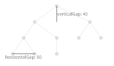
RTTreeLayout demonstrating gap sizes
Note that in the picture above the horizontalGap is applied only to the leaves of the tree; distance between parents is then accommodated automatically, so no overlapping or crossing occurs. The tree Layout orients the tree vertically, while the RTHorizontalTreeLayout uses an original orientation, from left to right.
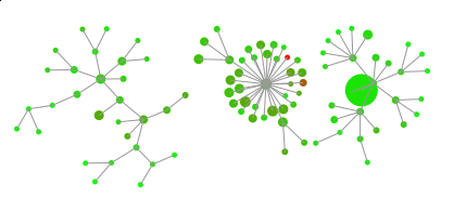
2.2. Radial Tree Layout
One problem with trees is that they tend to have many leaves which often results in very wide visualizations. One way to deal with this problem is to present the tree circularly. Since each new layer increases the radius of the circle, the overall element structure accommodates the space better.
	v := RTView new.
	elsBuilder := [ | es |
		es := (RTEllipse new size: 12) elementsOn: (1 to: 40).
		v addAll: es.

	RTEdgeBuilder new
		view: v;
		elements: es;
		connectFrom: [ :value | value // 2 ].

	RTMetricNormalizer new
		elements: es;
		normalizeColor: #yourself using: (Array with: Color red with: Color green).
	es
	].

	g := RTGroup with: elsBuilder value with: elsBuilder value with: elsBuilder value.

	RTTreeLayout new on: g first.
	RTHorizontalTreeLayout new on: g second.
	RTRadialTreeLayout new on: g third.

	RTRectanglePackLayout new gap: 0.1; on: g.
	v
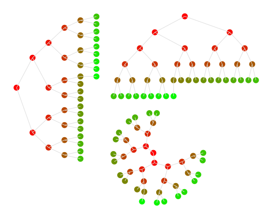
Horizontal, Vertical and Radial Tree Layouts
Note that RTRadialTreeLayout may produce an odd result in the presence of edge cycles.
2.3. Dominance Tree Layout
This layout is especially useful for visualizing dependencies and flow charts, since it organizes elements in such a manner that the flow of the graph is emphasized.
	v := RTView new.
	v @ RTDraggableView @ RTZoomableView.
	classes := RTShape withAllSubclasses asGroup.
	es := (RTEllipse new size: 15; color: Color blue) elementsOn: classes.
	v addAll: es.

	eb := RTEdgeBuilder new.
	eb view: v; objects: classes.
	eb shape arrowedLine; color: Color red.
	eb
		connectFrom: #yourself toAll: #dependentClasses.

	RTDominanceTreeLayout new
		verticalGap: 30;
		horizontalGap: 15;
		on: es.
	v
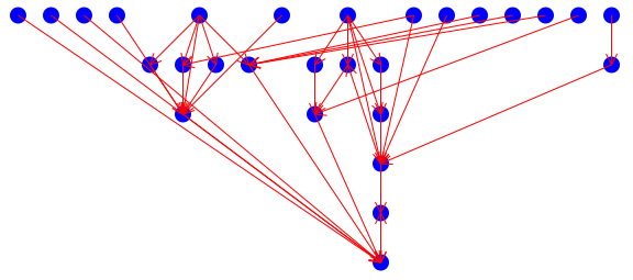
RTDominanceTreeLayout showing dependencies between RTShape classes
2.4. Cluster Layout
Cluster is visually similar to radial tree; it groups related elements together (Figure 2.4:.
	view := RTView new.
	view @ RTDraggableView  @ RTZoomableView.

	es := (RTEllipse new size: 12) elementsOn: (4 to: 100).
	view addAll: es.

	edges := RTGroup new.
	es copy do: [ :e |
		| fromE |
		fromE := es elementFromModel: (e model // 2).
		fromE ifNotNil: [ edges add: (RTLine edgeFrom: fromE to: e) ].
		].
	view addAll: edges.

	colorize := nil.
	colorize := [ :root :color |
	root outgoingEdges do: [ :edge |
		edge shape color: color.
		edge signalUpdate.
		colorize value: edge to value: color.
		].
	].

	colorize value: es first value: Color red.
	colorize value: es second value: Color green.
	colorize value: es third value: Color blue.
	colorize value: es fourth value: Color orange.

	RTClusterLayout new on: es.
	view
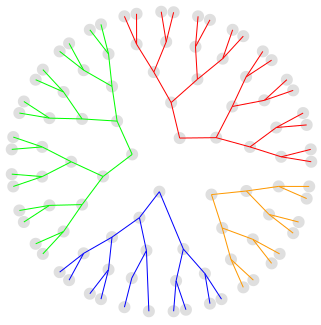
The difference between the cluster and radial layouts has to do with the layers forming circles.
2.5. Sugiyama
Sugiyama layout is a hierarchical layered layout. It places elements in hierarchical order such that edges goes from higher layer to lower layer. At the same time the layout minimizes the amount of layers and edge crossings (Figure 2.5).
	classes := RTLayout withAllSubclasses.
	b := RTMondrian new.
	b shape ellipse color: Color purple; size: 5.
	b nodes: classes.
	b edges connectFrom: #superclass.
	b layout sugiyama.
	b
2.6. Force Based Layout
Force Based Layout applies force between related elements similar to electrical charge. Thus related elements will repulse each other. The charge is usually negative since it represents repulsion.
Additionally to charge: you can also specify strength:, which is the strength of the bonds (edges) between elements.
	v := RTView new.

	es := RTEllipse elementsOn: Collection withAllSubclasses.
	v addAll: es.

	RTEdgeBuilder new
		elements: es;
		view: v;
		moveBehind;
		connectToAll: #dependentClasses.

	RTForceBasedLayout on: es.

	RTMetricNormalizer new
		elements: es;
		normalizeColor: #numberOfMethods;
		normalizeSize: #numberOfMethods.
	v
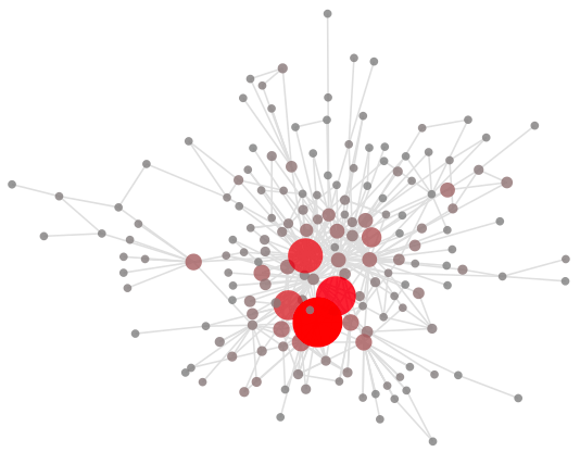
RTForceBasedLayout used to layout hierarchy of classes
The force based layout is appealing due to its simplicity of use and nice results that it produces. However, it badly scales. Performing a force based layout on hundreds of nodes and edges may take hours (literally). Before performing this layout on a large graph, one may want to try it on a reduced graph.
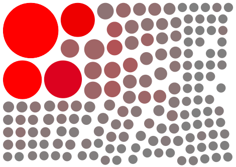
2.7. Rectangle Pack
RTRectanglePackLayout packs all the elements as tightly as possible. It uses an element's bounding box, so using circles or polygons instead of boxes will have no effect. One use for this layout is to provide comparative views of some elements — name clouds, source code size of classes, etc.
	v := RTView new.
	v addAll: ((RTEllipse new color: (Color red alpha: 0.3)) elementsOn: Collection withAllSubclasses) @ RTPopup.
	RTMetricNormalizer new
		elements: v elements;
		normalizeSize: #numberOfLinesOfCode min: 10 max: 60;
		normalizeColor: #numberOfMethods using: (Array with: Color gray with: Color red ).
	RTRectanglePackLayout on: v elements.
	v
RTNameCloud also internally uses RTRectanglePackLayout
	b := RTNameCloud new
		addString: 'open
		| v shape |
		v := RTView new.
		shape := RTLabel new height: [ :assoc | assoc value ]; text: #key.
		v addAll: (shape elementsOn: table associations).
		RTFlowLayout on: v elements.
		v open'.
	b
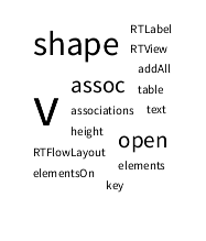
RTRectanglePackLayout used to layout a name cloud
3. Layout builder
The class RTLayoutBuilder offers expressive ways to build and compose layouts. The layout builder is offered by Mondrian. Consider the following Mondrian script (Figure 3.1):
	b := RTMondrian new.
	b nodes: RTShape withAllSubclasses.
	b shape line color: Color blue trans.
	b edges
		connectToAll: [ :c | c dependentClasses copyWithout: c superclass ].
	b layout
		force.
	b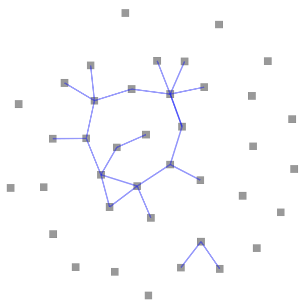
The script represents each subclass of RTShape as a box. Edges represents dependencies between classes, without considering inheritance. We made this example to produce lonely classes. It often happens that lonely classes need a particular layout.
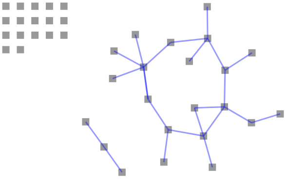
The message ifNotConnectedThen: takes as argument a layout (i.e., an instance of a subclass of RTLayout). The provided layout is applied only to elements that are not connected (i.e., with no incoming or outgoing edges).
	b := RTMondrian new.
	b nodes: RTShape withAllSubclasses.
	b shape line color: Color blue trans.
	b edges
		connectToAll: [ :c | c dependentClasses copyWithout: c superclass ].
	b layout
		force;
		ifNotConnectedThen: RTGridLayout new.
	b
Using the composition of layout and the layout builder (Figure 3.3):
	classes := RTLayout withAllSubclasses, RTBuilder withAllSubclasses, RTShape withAllSubclasses.

	b := RTMondrian new.
	b shape circle size: 5.
	b nodes: classes.
	b edges connectFrom: #superclass.

	b normalizer
		objects: classes;
		normalizeSize: #numberOfMethods min: 5 max: 30;
		normalizeColor: #numberOfLinesOfCode using: (Array with: Color green with: Color red ) using: #sqrt.

	b layout
		for: [ :c | c includesBehavior: RTLayout ] use: RTForceBasedLayout new;
		for: [ :c | c includesBehavior: RTBuilder ] use: RTForceBasedLayout new;
		for: [ :c | c includesBehavior: RTShape ] use: RTForceBasedLayout new;
		flow.
	b
RTForceBasedLayout used to layout hierarchy of classes
Several layouts are available:
-
forcefor a force based layout (also called spring layout) -
horizontalLinefor the horizontal line layout -
verticalLineto vertically line up elements -
treeto have a vertical tree -
horizontalTreefor an horizontal tree, roots are on the left-hand side and leaves on the right-hand side -
clusterandradialfor radial-based layout -
sugiyamafor the Sugiyama layout, which is a vertical tree layout that minimizes edges crossing
4. Creating custom layout
If you want to add your own layout you just need to subclass RTLayout and implement RTLayout>>doExecute: elements.
For more fine-graded control you have three main methods available.
	RTLayout>>executeOnElements: elements
		self doInitialize: elements.
		self doExecute: elements asOrderedCollection.
		self doPost: elements.
-
doInitialize:can be used for element preprocessing, if needed. For exampleRTAbstractGraphLayoutuses this for removing cycles from the graph, so the layouts can work only with trees. -
doExecute:is the main method, and the only method that must be implemented. Perform your layout here. -
doPost:allows one to insert post-processing actions.