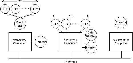
The environments with the greatest abstraction are at the system level. These environments view designs as collections of large functional units. The units can be arbitrarily complex, and they typically form the major components of a computer system (see Fig. 2.3). Connections in these designs also can be arbitrarily complex, carrying unspecified numbers of signals that use unspecified protocols. The reason for this is that, at a system level, the design is done by machine architects, so the precise method of communication is not important. All that matters is whether or not a particular function block connects to another. Sometimes the abstract nature of a connection is specified, such as whether it carries data or control. Often, however, a system-level environment exists only to show design topology without providing excessive detail.
 |
| FIGURE 2.3 System design. Major components are informally drawn and connected. |
The best example of a system-level environment is PMS [Bell and Newell]. PMS stands for "processor-memory-switch," three of the components in this environment (see Fig. 2.4). In addition to processors, memories, and switches, this environment has components for links, data operations, transducers, and control units. Solid lines are used to connect two components tightly, whereas dashed lines indicate secondary, control connections. Hierarchy can be used by defining new components that are collections of existing ones. The following paragraphs describe the seven primitives of the PMS environment.
| ||||||||||||||
| FIGURE 2.4 PMS components. |
The processor component (P) is used to represent the central processing element of a computer. This includes the instruction fetch, decode, and execution but does not include the instruction or data memory, nor any of the input/output (I/O) devices. This distinction can be difficult because some processors have built-in memory for stacks, caches, or microinstruction sets and, in these cases, the memory is considered to be part of the processor component. Also, all internal state such as machine registers and status bits are part of the processor. The intention is to encapsulate a component that is typically indivisible and the same in any less abstract environment.
Memory components (M) are generally connected to processors. Although the precise amount of memory need not be specified, the nature of the memory is given as a subscript on the component letter. For example, Mp indicates primary memory, which might distinguish it from secondary memory, fast memory, double-ported memory, or any other scheme in a given PMS diagram.
A switch (S) is a general component for joining multiple objects in a controllable fashion. Switches can be used to select among multiple I/O devices on a processor, multiple memories, or even multiple processor components. Their presence in a PMS diagram indicates that there is a choice in the use of the connecting components.
The link (L) is used to indicate an unusual connection configuration. For example, the connection of two separate processors is frequently done with some sort of link that moves information across physical distances. Buses, networks, and telephone lines are all links. Some processors do not need links to communicate if, for example, they share memory or are directly connected with common internal state.
A data operation (D) is any functional block that generates data. The category includes processors but is really meant to cover those devices that perform input, such as digitizers and keypads. The opposite of a data operation is a transducer (T), which takes data and transforms them for some other use. All output devices are transducers, including printers, displays, and robots.
The final primitive component of the PMS environment is the control unit (K). A control unit is one that causes another component to function. Thus, to make a transducer or data operation work, a control unit is needed. Processors are the only other components that have control and so they can replace these control units in situations that demand more intelligence.
| The PMS notation has been used to describe the configuration of computer systems [Bell and Newell; Siewiorek, Bell and Newell]. It is particularly useful in describing computer networks because it shows the components concisely. Figure 2.5 shows a PMS diagram for the computer network of Fig. 2.3. Notice the informal use of subscripts to qualify components and superscripts to indicate repetition. |
|
PMS is a formal example of a systems-level environment. Many less formal environments are used for system description, such as the example in Fig. 2.3. There are also textual hardware-description languages that are able to express abstract structural descriptions [VanCleemput]. The important aspect of systems level environments is that design is independent of physical layout, describes gross functionality, and can be used to capture easily entire VLSI systems.
| Previous | Table of Contents | Next | Static Free Software |