|
 |
|
|
Circuit-level simulators determine the analog waveforms at particular nodes in the design [Nagel]. Circuit elements are modeled as transistors, resistors and wires with propagation delays determined by their geometric structure and the underlying technology. These simulators rely on basic physical principles and thus can be highly accurate and general.
Circuit-level simulators provide fine-grain detail about the waveforms at nodes in a design, at the expense of being slow and therefore unable to process very large designs in a reasonable amount of time. Generally, circuit-level simulation is used to check critical parts of a design, whereas overall simulation is left to a higher-level simulator. Circuit-level simulators provide detailed timing information (for example, worst-case input-to-output delays) and are profoundly affected by the design-implementation technology.
Circuit-level simulation actually begins in the node-extraction phase of static analysis. The node extractor must provide the simulator with the capacitance and resistance of the wires, transistors, and resistors that the design comprises so that the delays can be accurately determined (see the later section, Delay Modeling). The values of these parameters are determined by the technology and the geometric properties of the structures. Once the connectivity, resistance, and capacitance parameters are determined, the circuit-level simulator combines this information with built-in or user-supplied device models.
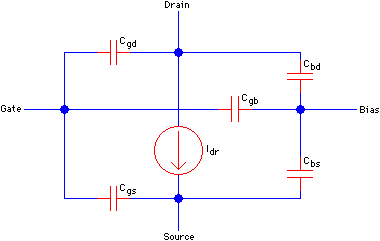
| A device model is a functional approximation of the behavior of an actual device. For example, Fig. 6.2 shows a typical model for a MOS transistor as used in the SHIELD simulator [Grundmann]. |
|
All this information is combined to produce a system of coupled, nonlinear differential equations that must be solved. Often, a so-called direct method is used, which is based on Newton's method, sparse-matrix techniques, and numerical integration [Nagel; IBM]. At each time step an initial guess at the node values is made based on the values at the previous time step. This guess is improved by iteration until some predetermined error tolerance is met, at which point the system records the values and moves on to the next time step. The direct method has the advantage that it can be used to simulate any electronic circuit. Its primary disadvantage is that the computation time is long for large circuits.
Other methods have been developed to decrease the computation time at the expense of generality. One key observation is that a circuit often may be partitioned into several sections that do not interact very much, or that interact in a limited fashion. Exploiting this observation and properties of particular technologies has led to the development of a class of circuit simulators based on relaxation techniques instead of on Newton's method. Relaxation methods have the advantage that they generally require less computation than does the direct method, but they are of use only for MOS circuits and can be significantly slower than the direct method where there is feedback in the design [Saleh, Kleckner, and Newton; Newton and Sangiovanni-Vincentelli; Hennion and Senn].
Regardless of method chosen, this relatively expensive computation is performed for each node in the system at each time step. This accounts for the relatively long running times of circuit-level simulators.
|
Previous |  |
Table of Contents | Next | |
Static Free Software |  |