


An electric current through a conductor will produce a magnetic field at right angles to the direction of electron flow. If that conductor is wrapped into a coil shape, the magnetic field produced will be oriented along the length of the coil. The greater the current, the greater the strength of the magnetic field, all other factors being equal:
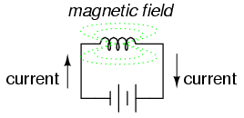
Inductors react against changes in current because of the energy stored in this magnetic field. When we construct a transformer from two inductor coils around a common iron core, we use this field to transfer energy from one coil to the other. However, there are simpler and more direct uses for electromagnetic fields than the applications we've seen with inductors and transformers. The magnetic field produced by a coil of current-carrying wire can be used to exert a mechanical force on any magnetic object, just as we can use a permanent magnet to attract magnetic objects, except that this magnet (formed by the coil) can be turned on or off by switching the current on or off through the coil.
If we place a magnetic object near such a coil for the purpose of making that object move when we energize the coil with electric current, we have what is called a solenoid. The movable magnetic object is called an armature, and most armatures can be moved with either direct current (DC) or alternating current (AC) energizing the coil. The polarity of the magnetic field is irrelevant for the purpose of attracting an iron armature. Solenoids can be used to electrically open door latches, open or shut valves, move robotic limbs, and even actuate electric switch mechanisms. However, if a solenoid is used to actuate a set of switch contacts, we have a device so useful it deserves its own name: the relay.
Relays are extremely useful when we have a need to control a large amount of current and/or voltage with a small electrical signal. The relay coil which produces the magnetic field may only consume fractions of a watt of power, while the contacts closed or opened by that magnetic field may be able to conduct hundreds of times that amount of power to a load. In effect, a relay acts as a binary (on or off) amplifier.
Just as with transistors, the relay's ability to control one electrical signal with another finds application in the construction of logic functions. This topic will be covered in greater detail in another lesson. For now, the relay's "amplifying" ability will be explored.
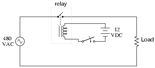
In the above schematic, the relay's coil is energized by the low-voltage (12 VDC) source, while the single-pole, single-throw (SPST) contact interrupts the high-voltage (480 VAC) circuit. It is quite likely that the current required to energize the relay coil will be hundreds of times less than the current rating of the contact. Typical relay coil currents are well below 1 amp, while typical contact ratings for industrial relays are at least 10 amps.
One relay coil/armature assembly may be used to actuate more than one set of contacts. Those contacts may be normally-open, normally-closed, or any combination of the two. As with switches, the "normal" state of a relay's contacts is that state when the coil is de-energized, just as you would find the relay sitting on a shelf, not connected to any circuit.
Relay contacts may be open-air pads of metal alloy, mercury tubes, or even magnetic reeds, just as with other types of switches. The choice of contacts in a relay depends on the same factors which dictate contact choice in other types of switches. Open-air contacts are the best for high-current applications, but their tendency to corrode and spark may cause problems in some industrial environments. Mercury and reed contacts are sparkless and won't corrode, but they tend to be limited in current-carrying capacity.
Shown here are three small relays (about two inches in height, each), installed on a panel as part of an electrical control system at a municipal water treatment plant:
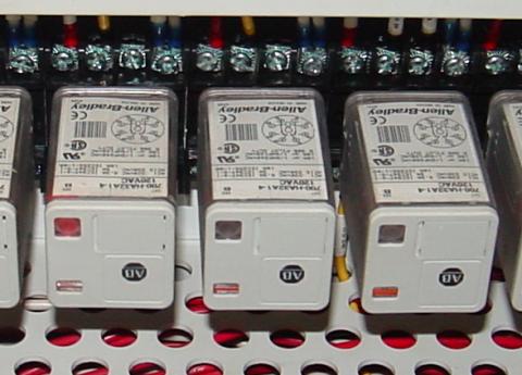
The relay units shown here are called "octal-base," because they plug into matching sockets, the electrical connections secured via eight metal pins on the relay bottom. The screw terminal connections you see in the photograph where wires connect to the relays are actually part of the socket assembly, into which each relay is plugged. This type of construction facilitates easy removal and replacement of the relay(s) in the event of failure.
Aside from the ability to allow a relatively small electric signal to switch a relatively large electric signal, relays also offer electrical isolation between coil and contact circuits. This means that the coil circuit and contact circuit(s) are electrically insulated from one another. One circuit may be DC and the other AC (such as in the example circuit shown earlier), and/or they may be at completely different voltage levels, across the connections or from connections to ground.
While relays are essentially binary devices, either being completely on or completely off, there are operating conditions where their state may be indeterminate, just as with semiconductor logic gates. In order for a relay to positively "pull in" the armature to actuate the contact(s), there must be a certain minimum amount of current through the coil. This minimum amount is called the pull-in current, and it is analogous to the minimum input voltage that a logic gate requires to guarantee a "high" state (typically 2 Volts for TTL, 3.5 Volts for CMOS). Once the armature is pulled closer to the coil's center, however, it takes less magnetic field flux (less coil current) to hold it there. Therefore, the coil current must drop below a value significantly lower than the pull-in current before the armature "drops out" to its spring-loaded position and the contacts resume their normal state. This current level is called the drop-out current, and it is analogous to the maximum input voltage that a logic gate input will allow to guarantee a "low" state (typically 0.8 Volts for TTL, 1.5 Volts for CMOS).
The hysteresis, or difference between pull-in and drop-out currents, results in operation that is similar to a Schmitt trigger logic gate. Pull-in and drop-out currents (and voltages) vary widely from relay to relay, and are specified by the manufacturer.
When a relay is used to switch a large amount of electrical power through its contacts, it is designated by a special name: contactor. Contactors typically have multiple contacts, and those contacts are usually (but not always) normally-open, so that power to the load is shut off when the coil is de-energized. Perhaps the most common industrial use for contactors is the control of electric motors.
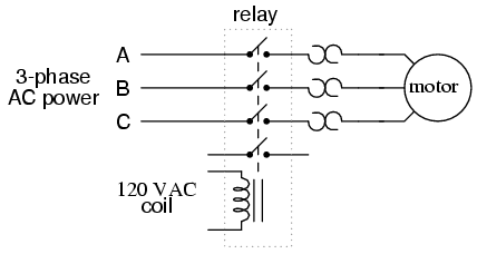
The top three contacts switch the respective phases of the incoming 3-phase AC power, typically at least 480 Volts for motors 1 horsepower or greater. The lowest contact is an "auxiliary" contact which has a current rating much lower than that of the large motor power contacts, but is actuated by the same armature as the power contacts. The auxiliary contact is often used in a relay logic circuit, or for some other part of the motor control scheme, typically switching 120 Volt AC power instead of the motor voltage. One contactor may have several auxiliary contacts, either normally-open or normally-closed, if required.
The three "opposed-question-mark" shaped devices in series with each phase going to the motor are called overload heaters. Each "heater" element is a low-resistance strip of metal intended to heat up as the motor draws current. If the temperature of any of these heater elements reaches a critical point (equivalent to a moderate overloading of the motor), a normally-closed switch contact (not shown in the diagram) will spring open. This normally-closed contact is usually connected in series with the relay coil, so that when it opens the relay will automatically de-energize, thereby shutting off power to the motor. We will see more of this overload protection wiring in the next chapter. Overload heaters are intended to provide overcurrent protection for large electric motors, unlike circuit breakers and fuses which serve the primary purpose of providing overcurrent protection for power conductors.
Overload heater function is often misunderstood. They are not fuses; that is, it is not their function to burn open and directly break the circuit as a fuse is designed to do. Rather, overload heaters are designed to thermally mimic the heating characteristic of the particular electric motor to be protected. All motors have thermal characteristics, including the amount of heat energy generated by resistive dissipation (I2R), the thermal transfer characteristics of heat "conducted" to the cooling medium through the metal frame of the motor, the physical mass and specific heat of the materials constituting the motor, etc. These characteristics are mimicked by the overload heater on a miniature scale: when the motor heats up toward its critical temperature, so will the heater toward its critical temperature, ideally at the same rate and approach curve. Thus, the overload contact, in sensing heater temperature with a thermo-mechanical mechanism, will sense an analogue of the real motor. If the overload contact trips due to excessive heater temperature, it will be an indication that the real motor has reached its critical temperature (or, would have done so in a short while). After tripping, the heaters are supposed to cool down at the same rate and approach curve as the real motor, so that they indicate an accurate proportion of the motor's thermal condition, and will not allow power to be re-applied until the motor is truly ready for start-up again.
Shown here is a contactor for a three-phase electric motor, installed on a panel as part of an electrical control system at a municipal water treatment plant:

Three-phase, 480 volt AC power comes in to the three normally-open contacts at the top of the contactor via screw terminals labeled "L1," "L2," and "L3" (The "L2" terminal is hidden behind a square-shaped "snubber" circuit connected across the contactor's coil terminals). Power to the motor exits the overload heater assembly at the bottom of this device via screw terminals labeled "T1," "T2," and "T3."
The overload heater units themselves are black, square-shaped blocks with the label "W34," indicating a particular thermal response for a certain horsepower and temperature rating of electric motor. If an electric motor of differing power and/or temperature ratings were to be substituted for the one presently in service, the overload heater units would have to be replaced with units having a thermal response suitable for the new motor. The motor manufacturer can provide information on the appropriate heater units to use.
A white pushbutton located between the "T1" and "T2" line heaters serves as a way to manually re-set the normally-closed switch contact back to its normal state after having been tripped by excessive heater temperature. Wire connections to the "overload" switch contact may be seen at the lower-right of the photograph, near a label reading "NC" (normally-closed). On this particular overload unit, a small "window" with the label "Tripped" indicates a tripped condition by means of a colored flag. In this photograph, there is no "tripped" condition, and the indicator appears clear.
As a footnote, heater elements may be used as a crude current shunt resistor for determining whether or not a motor is drawing current when the contactor is closed. There may be times when you're working on a motor control circuit, where the contactor is located far away from the motor itself. How do you know if the motor is consuming power when the contactor coil is energized and the armature has been pulled in? If the motor's windings are burnt open, you could be sending voltage to the motor through the contactor contacts, but still have zero current, and thus no motion from the motor shaft. If a clamp-on ammeter isn't available to measure line current, you can take your multimeter and measure millivoltage across each heater element: if the current is zero, the voltage across the heater will be zero (unless the heater element itself is open, in which case the voltage across it will be large); if there is current going to the motor through that phase of the contactor, you will read a definite millivoltage across that heater:

This is an especially useful trick to use for troubleshooting 3-phase AC motors, to see if one phase winding is burnt open or disconnected, which will result in a rapidly destructive condition known as "single-phasing." If one of the lines carrying power to the motor is open, it will not have any current through it (as indicated by a 0.00 mV reading across its heater), although the other two lines will (as indicated by small amounts of voltage dropped across the respective heaters).
Some relays are constructed with a kind of "shock absorber" mechanism attached to the armature which prevents immediate, full motion when the coil is either energized or de-energized. This addition gives the relay the property of time-delay actuation. Time-delay relays can be constructed to delay armature motion on coil energization, de-energization, or both.
Time-delay relay contacts must be specified not only as either normally-open or normally-closed, but whether the delay operates in the direction of closing or in the direction of opening. The following is a description of the four basic types of time-delay relay contacts.
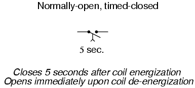
First we have the normally-open, timed-closed (NOTC) contact. This type of contact is normally open when the coil is unpowered (de-energized). The contact is closed by the application of power to the relay coil, but only after the coil has been continuously powered for the specified amount of time. In other words, the direction of the contact's motion (either to close or to open) is identical to a regular NO contact, but there is a delay in closing direction. Because the delay occurs in the direction of coil energization, this type of contact is alternatively known as a normally-open, on-delay:
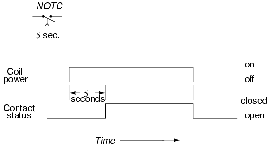
The following is a timing diagram of this relay contact's operation:
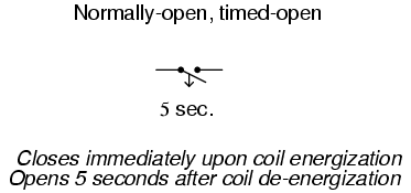
Next we have the normally-open, timed-open (NOTO) contact. Like the NOTC contact, this type of contact is normally open when the coil is unpowered (de-energized), and closed by the application of power to the relay coil. However, unlike the NOTC contact, the timing action occurs upon de-energization of the coil rather than upon energization. Because the delay occurs in the direction of coil de-energization, this type of contact is alternatively known as a normally-open, off-delay:
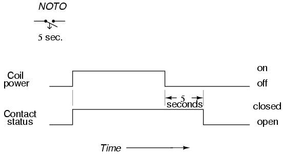
The following is a timing diagram of this relay contact's operation:
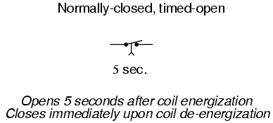
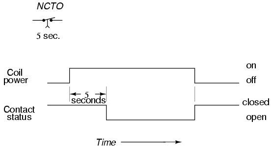
Next we have the normally-closed, timed-open (NCTO) contact. This type of contact is normally closed when the coil is unpowered (de-energized). The contact is opened with the application of power to the relay coil, but only after the coil has been continuously powered for the specified amount of time. In other words, the direction of the contact's motion (either to close or to open) is identical to a regular NC contact, but there is a delay in the opening direction. Because the delay occurs in the direction of coil energization, this type of contact is alternatively known as a normally-closed, on-delay:
The following is a timing diagram of this relay contact's operation:
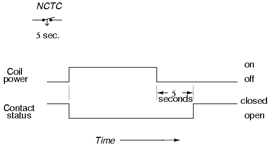
Finally we have the normally-closed, timed-closed (NCTC) contact. Like the NCTO contact, this type of contact is normally closed when the coil is unpowered (de-energized), and opened by the application of power to the relay coil. However, unlike the NCTO contact, the timing action occurs upon de-energization of the coil rather than upon energization. Because the delay occurs in the direction of coil de-energization, this type of contact is alternatively known as a normally-closed, off-delay:

The following is a timing diagram of this relay contact's operation:
Time-delay relays are very important for use in industrial control logic circuits. Some examples of their use include:
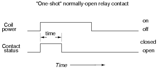
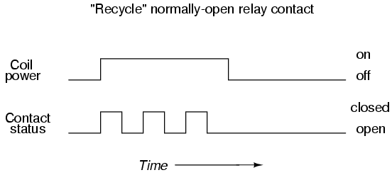
The older, mechanical time-delay relays used pneumatic dashpots or fluid-filled piston/cylinder arrangements to provide the "shock absorbing" needed to delay the motion of the armature. Newer designs of time-delay relays use electronic circuits with resistor-capacitor (RC) networks to generate a time delay, then energize a normal (instantaneous) electromechanical relay coil with the electronic circuit's output. The electronic-timer relays are more versatile than the older, mechanical models, and less prone to failure. Many models provide advanced timer features such as "one-shot" (one measured output pulse for every transition of the input from de-energized to energized), "recycle" (repeated on/off output cycles for as long as the input connection is energized) and "watchdog" (changes state if the input signal does not repeatedly cycle on and off).
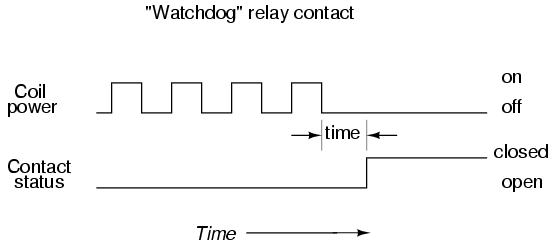
The "watchdog" timer is especially useful for monitoring of computer systems. If a computer is being used to control a critical process, it is usually recommended to have an automatic alarm to detect computer "lockup" (an abnormal halting of program execution due to any number of causes). An easy way to set up such a monitoring system is to have the computer regularly energize and de-energize the coil of a watchdog timer relay (similar to the output of the "recycle" timer). If the computer execution halts for any reason, the signal it outputs to the watchdog relay coil will stop cycling and freeze in one or the other state. A short time thereafter, the watchdog relay will "time out" and signal a problem.
A special type of relay is one which monitors the current, voltage, frequency, or any other type of electric power measurement either from a generating source or to a load for the purpose of triggering a circuit breaker to open in the event of an abnormal condition. These relays are referred to in the electrical power industry as protective relays.
The circuit breakers which are used to switch large quantities of electric power on and off are actually electromechanical relays, themselves. Unlike the circuit breakers found in residential and commercial use which determine when to trip (open) by means of a bimetallic strip inside that bends when it gets too hot from overcurrent, large industrial circuit breakers must be "told" by an external device when to open. Such breakers have two electromagnetic coils inside: one to close the breaker contacts and one to open them. The "trip" coil can be energized by one or more protective relays, as well as by hand switches, connected to switch 125 Volt DC power. DC power is used because it allows for a battery bank to supply close/trip power to the breaker control circuits in the event of a complete (AC) power failure.
Protective relays can monitor large AC currents by means of current transformers (CT's), which encircle the current-carrying conductors exiting a large circuit breaker, transformer, generator, or other device. Current transformers step down the monitored current to a secondary (output) range of 0 to 5 amps AC to power the protective relay. The current relay uses this 0-5 amp signal to power its internal mechanism, closing a contact to switch 125 Volt DC power to the breaker's trip coil if the monitored current becomes excessive.
Likewise, (protective) voltage relays can monitor high AC voltages by means of voltage, or potential, transformers (PT's) which step down the monitored voltage to a secondary range of 0 to 120 Volts AC, typically. Like (protective) current relays, this voltage signal powers the internal mechanism of the relay, closing a contact to switch 125 Volt DC power to the breaker's trip coil is the monitored voltage becomes excessive.
There are many types of protective relays, some with highly specialized functions. Not all monitor voltage or current, either. They all, however, share the common feature of outputting a contact closure signal which can be used to switch power to a breaker trip coil, close coil, or operator alarm panel. Most protective relay functions have been categorized into an ANSI standard number code. Here are a few examples from that code list:
ANSI protective relay designation numbers
12 = Overspeed
24 = Overexcitation
25 = Syncrocheck
27 = Bus/Line undervoltage
32 = Reverse power (anti-motoring)
38 = Stator overtemp (RTD)
39 = Bearing vibration
40 = Loss of excitation
46 = Negative sequence undercurrent (phase current imbalance)
47 = Negative sequence undervoltage (phase voltage imbalance)
49 = Bearing overtemp (RTD)
50 = Instantaneous overcurrent
51 = Time overcurrent
51V = Time overcurrent -- voltage restrained
55 = Power factor
59 = Bus overvoltage
60FL = Voltage transformer fuse failure
67 = Phase/Ground directional current
79 = Autoreclose
81 = Bus over/underfrequency
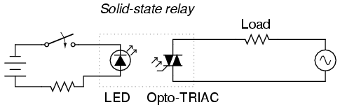
As versatile as electromechanical relays can be, they do suffer many limitations. They can be expensive to build, have a limited contact cycle life, take up a lot of room, and switch slowly, compared to modern semiconductor devices. These limitations are especially true for large power contactor relays. To address these limitations, many relay manufacturers offer "solid-state" relays, which use an SCR, TRIAC, or transistor output instead of mechanical contacts to switch the controlled power. The output device (SCR, TRIAC, or transistor) is optically-coupled to an LED light source inside the relay. The relay is turned on by energizing this LED, usually with low-voltage DC power. This optical isolation between input to output rivals the best that electromechanical relays can offer.
Being solid-state devices, there are no moving parts to wear out, and they are able to switch on and off much faster than any mechanical relay armature can move. There is no sparking between contacts, and no problems with contact corrosion. However, solid-state relays are still too expensive to build in very high current ratings, and so electromechanical contactors continue to dominate that application in industry today.
One significant advantage of a solid-state SCR or TRIAC relay over an electromechanical device is its natural tendency to open the AC circuit only at a point of zero load current. Because SCR's and TRIAC's are thyristors, their inherent hysteresis maintains circuit continuity after the LED is de-energized until the AC current falls below a threshold value (the holding current). In practical terms what this means is the circuit will never be interrupted in the middle of a sine wave peak. Such untimely interruptions in a circuit containing substantial inductance would normally produce large voltage spikes due to the sudden magnetic field collapse around the inductance. This will not happen in a circuit broken by an SCR or TRIAC. This feature is called zero-crossover switching.
One disadvantage of solid state relays is their tendency to fail "shorted" on their outputs, while electromechanical relay contacts tend to fail "open." In either case, it is possible for a relay to fail in the other mode, but these are the most common failures. Because a "fail-open" state is generally considered safer than a "fail-closed" state, electromechanical relays are still favored over their solid-state counterparts in many applications.
Lessons In Electric Circuits copyright (C) 2000-2007 Tony R. Kuphaldt, under the terms and conditions of the Design Science License.