 |
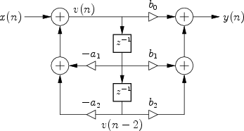
The signal flow graph for the Direct-Form-II (DF-II) realization of the second-order IIR filter section is shown in Fig.9.2.
The difference equation for the second-order DF-II structure can be written as

which can be interpreted as a two-pole filter followed in series by a two-zero filter. This contrasts with the DF-I structure of the previous section (diagrammed in Fig.9.1) in which the two-zero FIR section precedes the two-pole recursive section in series. Since LTI filters in series commute (§6.7), we may reverse this ordering, and implement an all-pole filter followed by an FIR filter in series. In other words, the zeros may come first, followed by the poles, without changing the transfer function. When this is done, it is easy to see that the delay elements in the two filter sections contain the same numbers (see Fig.5.1). As a result, a single delay line can be shared between the all-pole and all-zero (FIR) sections. This new combined structure is called ``direct form II'' [60, p. 153-155]. The second-order case is shown in Fig.9.2. It specifies exactly the same digital filter as shown in Fig.9.1 in the case of infinite-precision numerical computations.
In summary, the DF-II structure has the following properties: